Maximum Hosts per Network
Class C Network
Consider a Class C network with the IP address range:
-
192.168.1.0/24
(This range spans from 192.168.1.0 to 192.168.1.255.) -
Host Portion: The host portion in this case is 8 bits (the last octet).
- Calculation: (2^8 = 256) possible addresses.
-
Reserved Addresses:
- Network Address: 192.168.1.0
- Broadcast Address: 192.168.1.255
-
Usable Hosts:
- Maximum hosts = (2^8 - 2 = 254) hosts
Class B Network
For a Class B network with the IP address range:
-
172.16.0.0/16 to 172.16.255.255/16
-
Host Portion: The host portion here is 16 bits.
- Calculation: (2^{16} = 65,536) possible addresses.
-
Reserved Addresses:
- Network Address: 172.16.0.0
- Broadcast Address: 172.16.255.255
-
Usable Hosts:
- Maximum hosts = (2^{16} - 2 = 65,534) hosts
Class A Network
For a Class A network with the IP address range:
-
10.0.0.0/8 to 10.255.255.255/8
-
Host Portion: The host portion is 24 bits.
- Calculation: (2^{24} = 16,777,216) possible addresses.
-
Reserved Addresses:
- Network Address: 10.0.0.0
- Broadcast Address: 10.255.255.255
-
Usable Hosts:
- Maximum hosts = (2^{24} - 2 = 16,777,214) hosts
General Formula
The general formula to calculate the number of hosts on any network is:
[ \text{Maximum Hosts} = 2^N - 2 ]
Where (N) is the number of host bits.
First and Last Usable Addresses
Class C Network
For the network 192.168.1.0/24:
-
First Usable Address:
- Increment the host portion by 1:
- 192.168.1.1/24
-
Last Usable Address:
- Decrement the broadcast address by 1:
- 192.168.1.254/24
Class B Network
For the network 172.16.0.0/16:
-
First Usable Address:
- Increment the host portion by 1:
- 172.16.0.1/16
-
Last Usable Address:
- Decrement the broadcast address by 1:
- 172.16.255.254/16
Class A Network
For the network 10.0.0.0/8:
-
First Usable Address:
- Increment the host portion by 1:
- 10.0.0.1/8
-
Last Usable Address:
- Decrement the broadcast address by 1:
- 10.255.255.254/8
Cisco CLI Device Configuration
Initial Commands
-
Enable Command:
R1> enable R1# show ip interface brief -
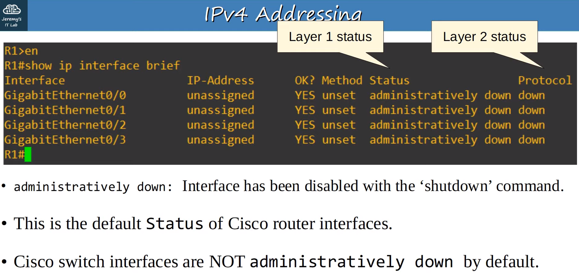
Show IP Interface Brief:
- This command lists interfaces, IP addresses, method of assignment, status, and protocol.
Fields:
- Interfaces: Available/connected port interfaces.
- IP Addresses: Assigned IP addresses.
- Method: Method used to assign IP addresses.
- Status (Layer 1): Shows if the interface is administratively down.
- Protocol (Layer 2): Shows protocol status (cannot be up if Layer 1 is down).
Configuring the Interface
-
Enter Configuration Mode:
R1# conf t -
Select Interface:
R1(config)# interface gigabitethernet 0/0- Can be shortened to
g0/0.
- Can be shortened to
-
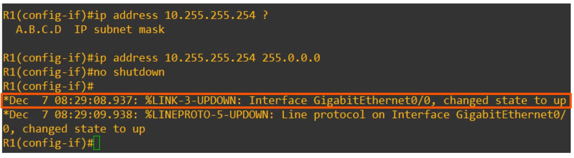
Set IP Address and Subnet Mask:
R1(config-if)# ip address 10.255.255.254 255.0.0.0 -
Enable the Interface:
R1(config-if)# no shutdown
Verify Configuration
- Show IP Interface Brief:
R1(config-if)# do show ip interface brief- Confirms that the interface is up and running.
Additional ‘Show’ CLI Commands
-
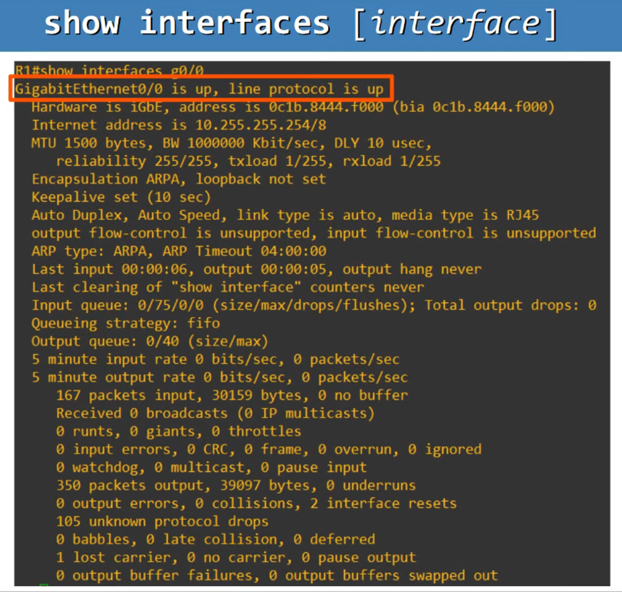
Show Interfaces:
show interfaces <interface name>- Provides detailed Layer 1, Layer 2, and some Layer 3 information.
- Displays MAC Address (BIA address) and IP Address.
-
Show Interfaces Description:
show interfaces description- Allows adding descriptions to interfaces.
Example:
R1(config)# int g0/0 R1(config)# description ## to SW1 ##- This will display in the description column:
Interface        Description
Gi0/0            ## to SW1 ##