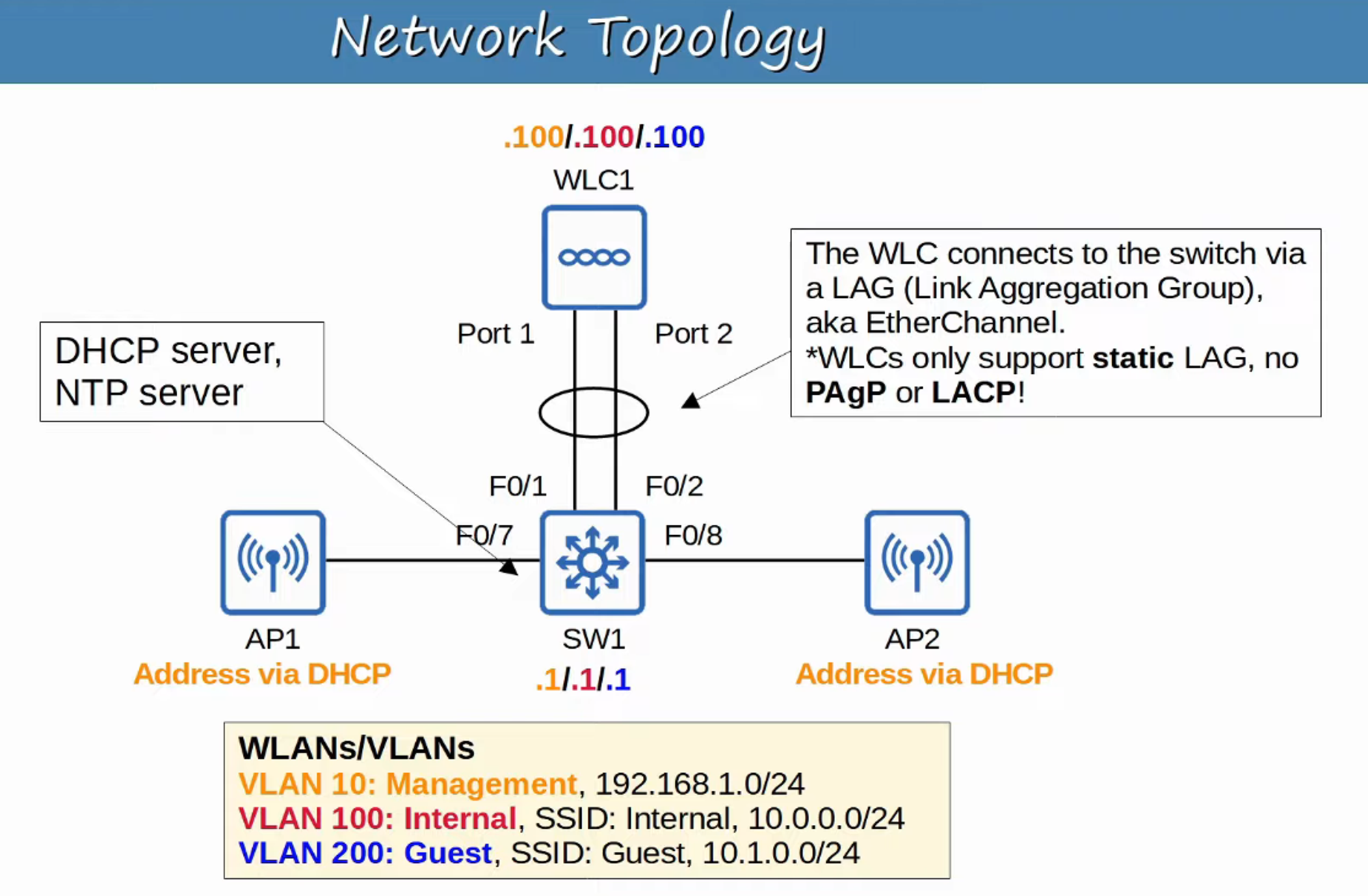
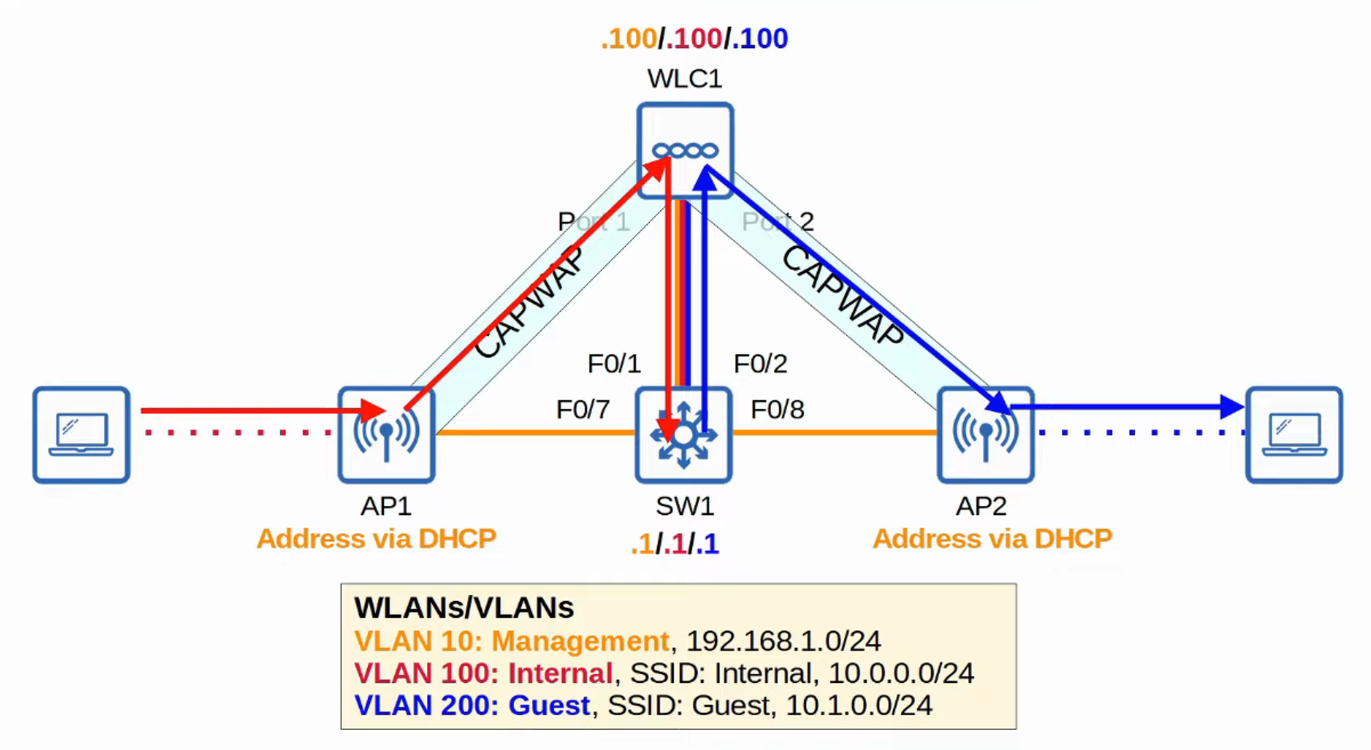
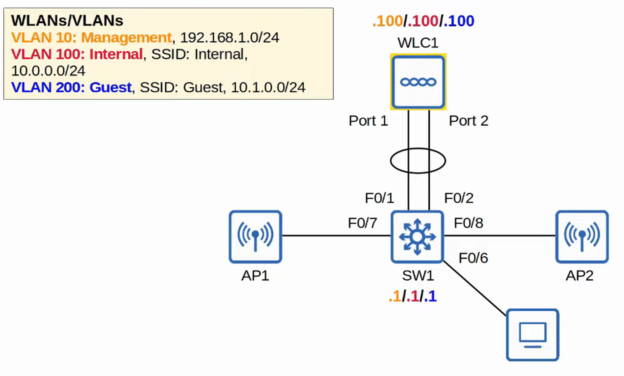
TOPOLOGY INTRODUCTION
INTERNAL PC (VLAN 100) ACCESSING DEFAULT GATEWAY via Internal CAPWAP tunnel
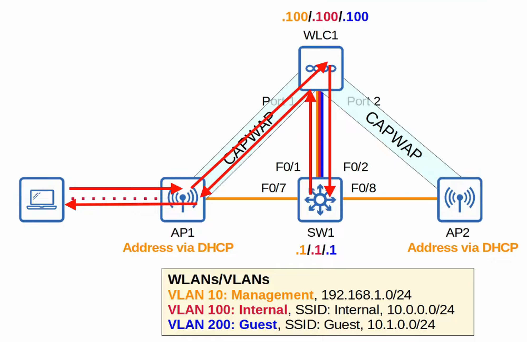
REACHING External GUEST PC via DEFAULT GATEWAY + Internal and External CAPWAP tunnels
LAYER 3 SWITCH CONFIGURATION (SW1)
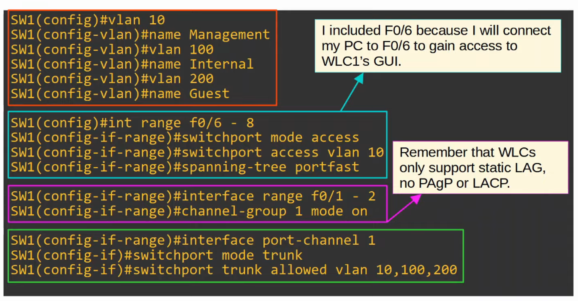
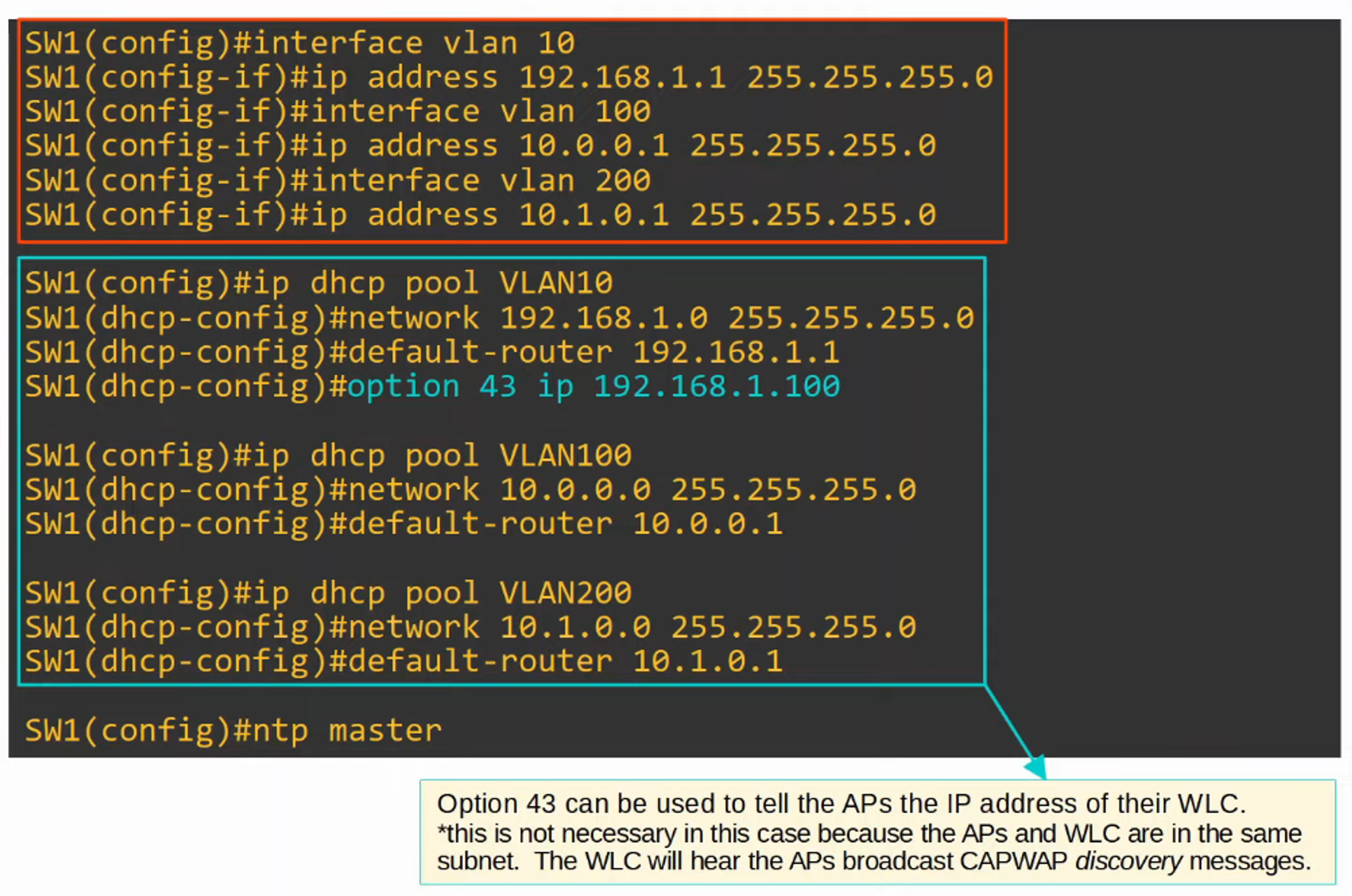
PART 2 of configuration
Note DHCP “Option 43”
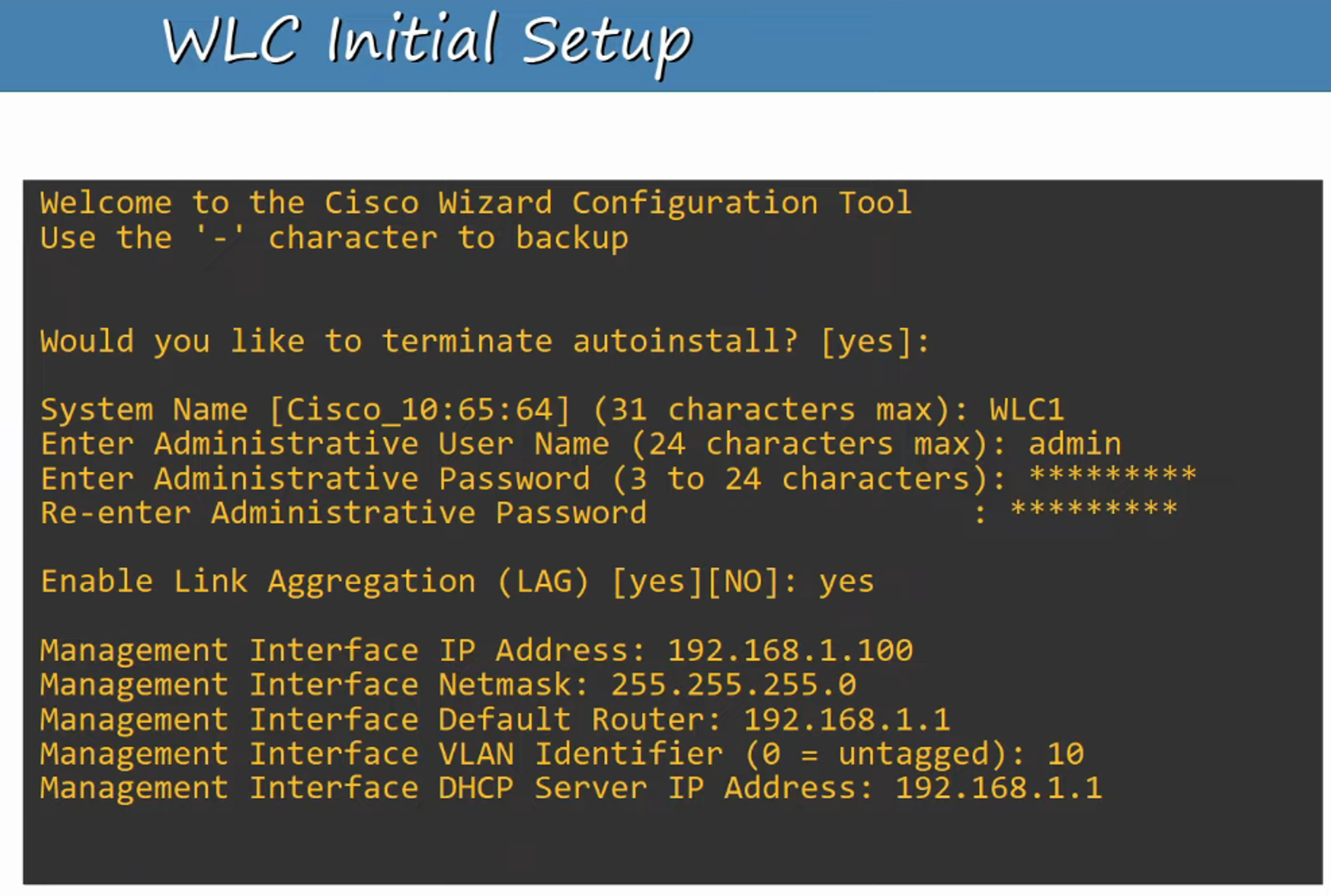
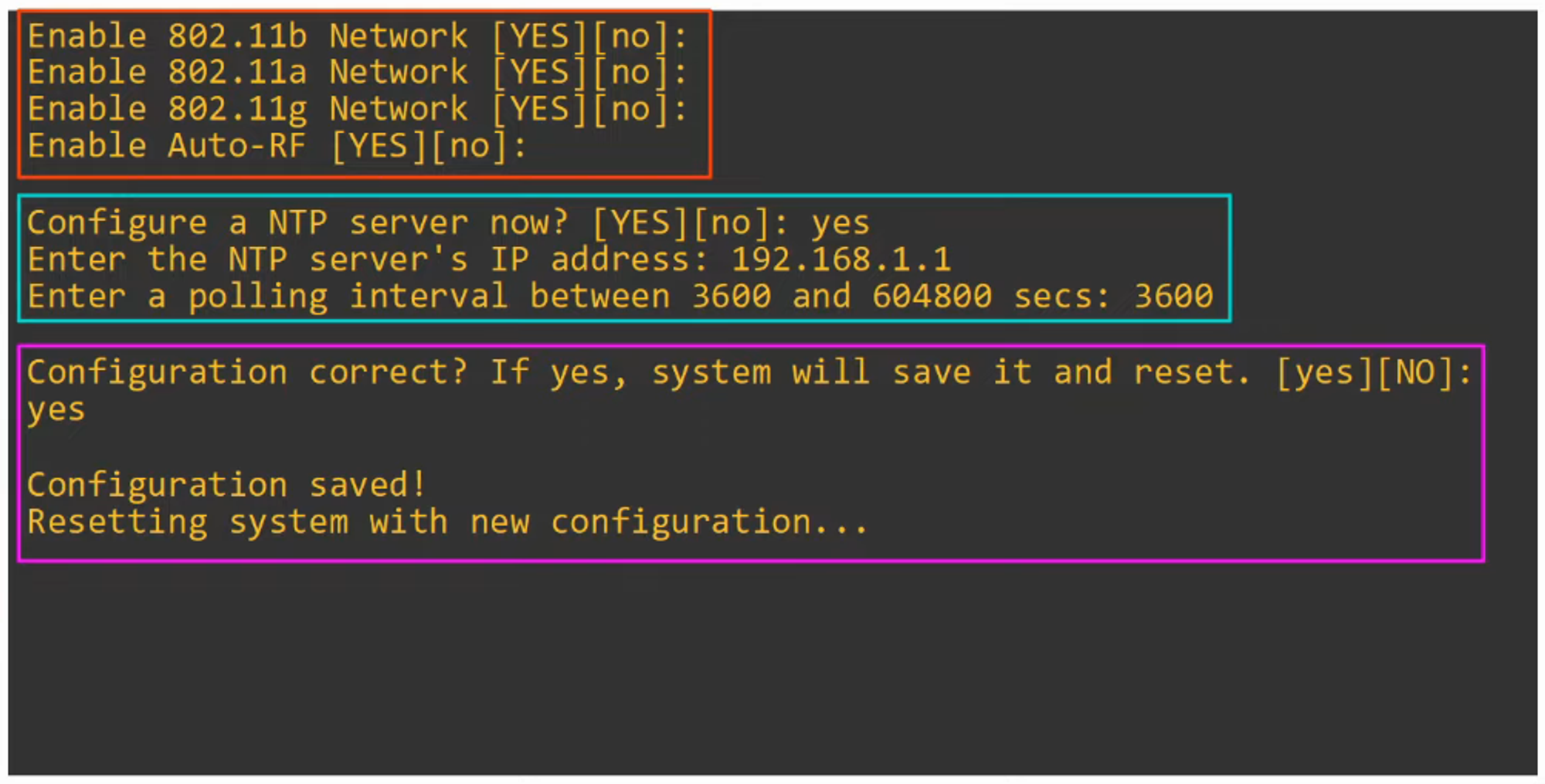
WLC SETUP
This helps set up the WLC to allow GUI configuration
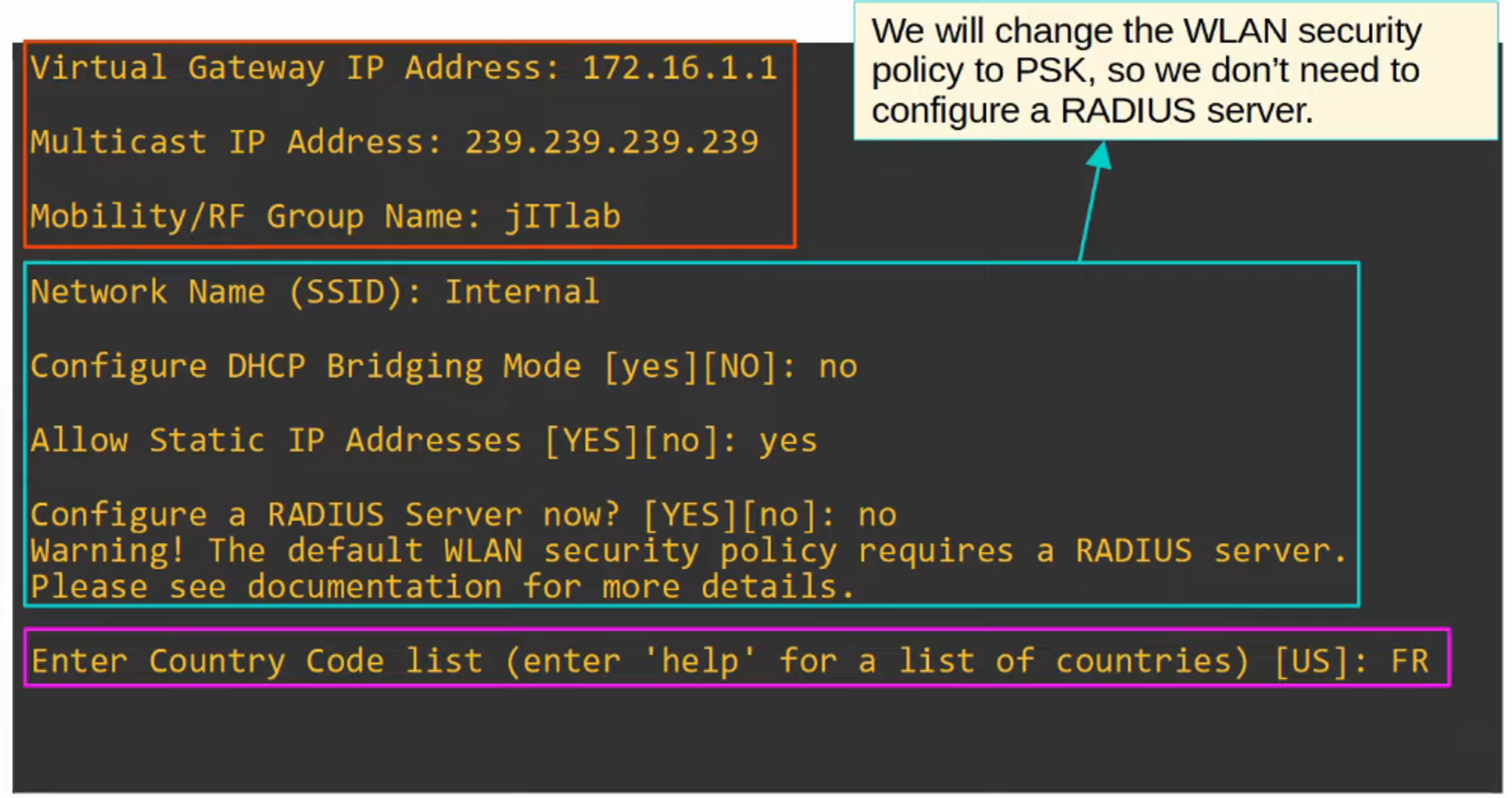
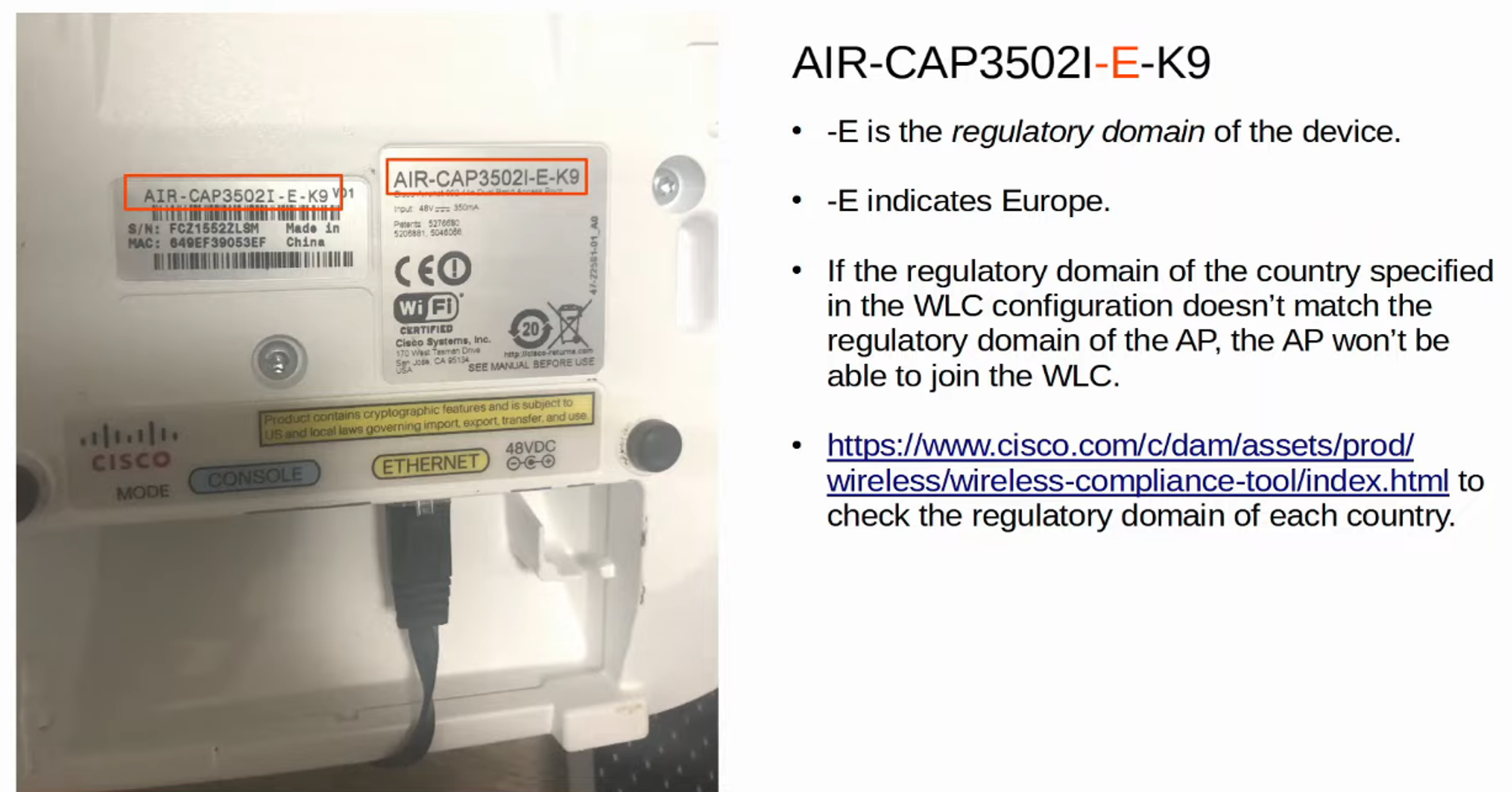
Why Jeremy chose FRANCE for Country Code (has to do with regulatory domain of equipment)
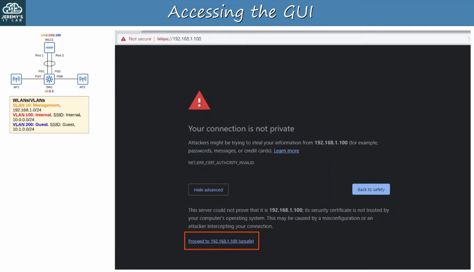
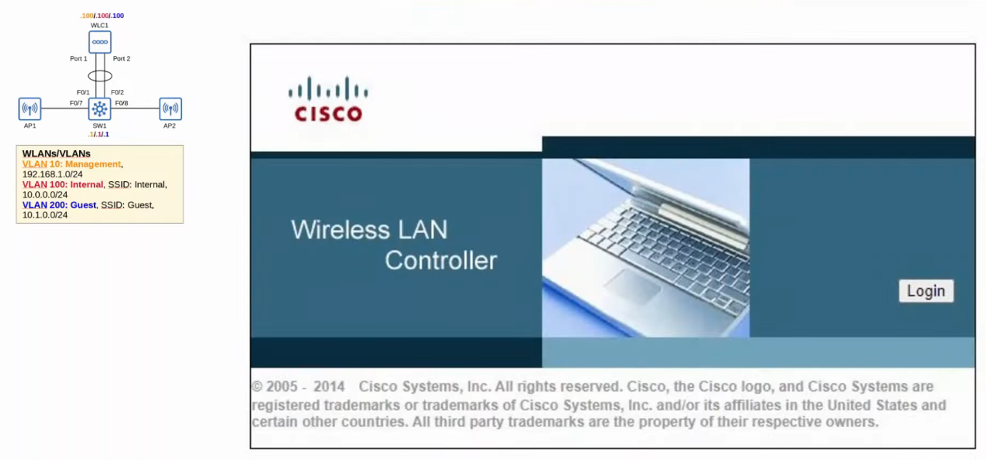
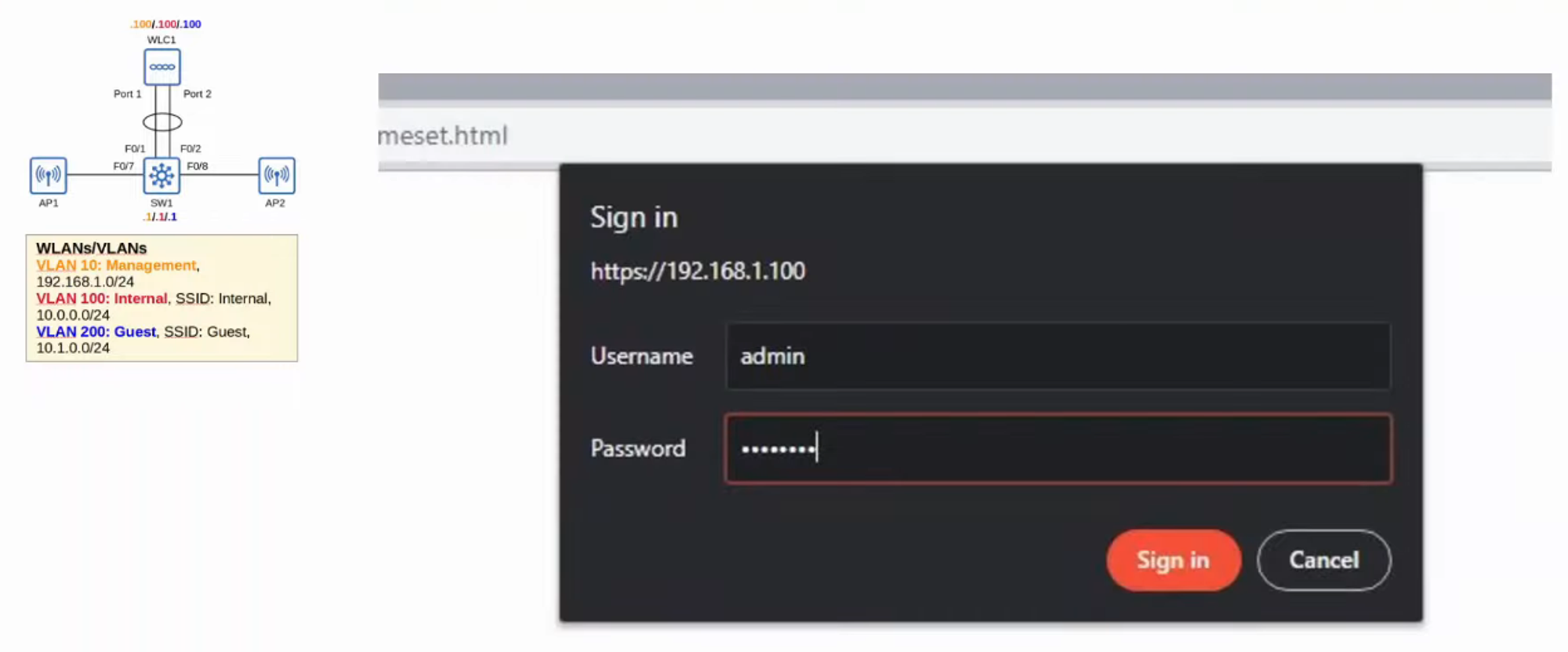
ACCESSING THE WLC GUI
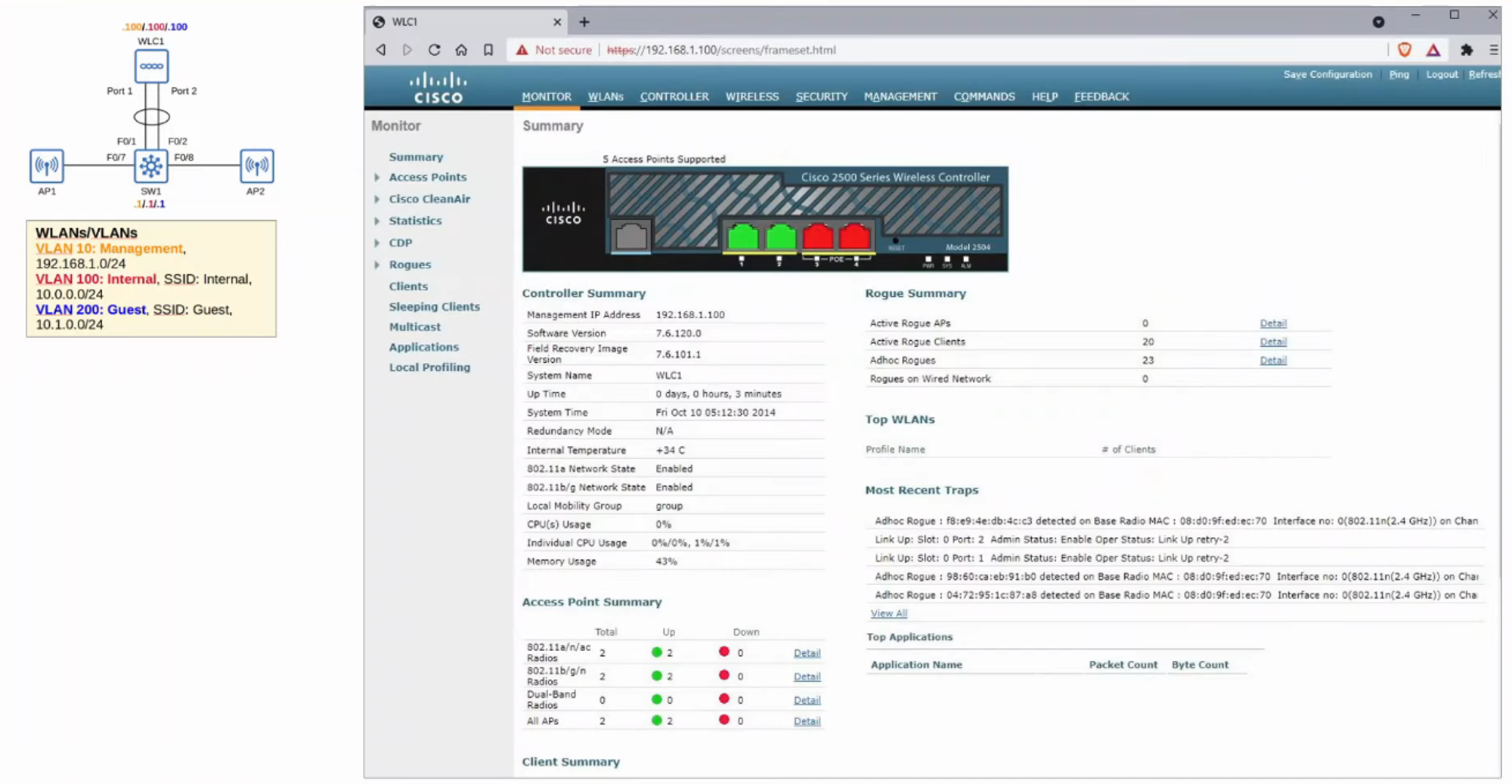
WLC CONFIGURATION
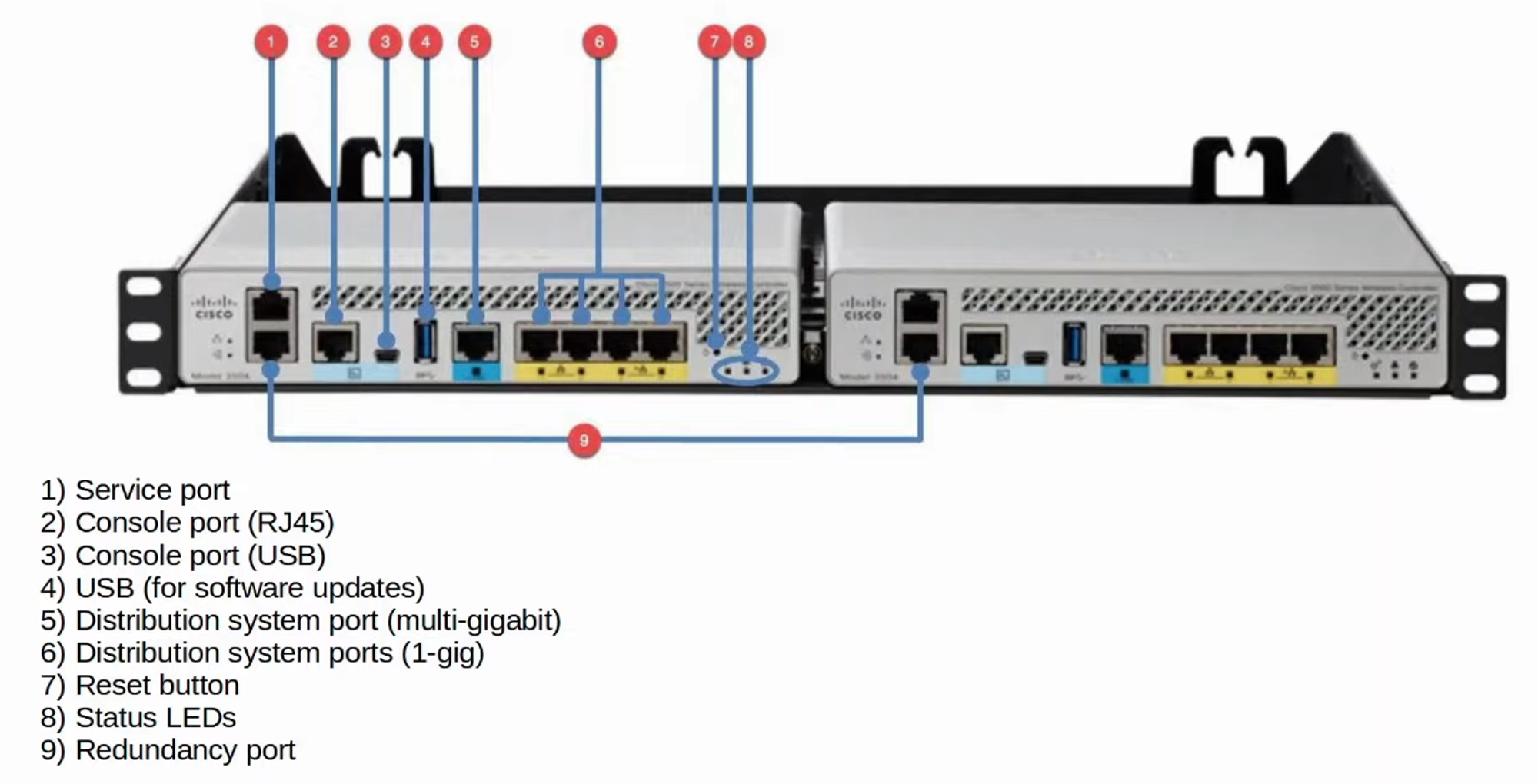
WLC PORTS
- WLC PORTS are the PHYSICAL PORTS that cables connect to
- WLC INTERFACES are the logical interfaces within the WLC (ie: SVIs on a SWITCH)
- WLCs have a few different PORTS:
- SERVICE PORT
- A dedicated MANAGEMENT PORT
- Used for OUT-OF-BAND management
- Must connected to a SWITCH ACCESS PORT because it only supports one VLAN
- This PORT can be used to connect to the DEVICE while it is booting, performing system recovery, etc.
- DISTRIBUTION SYSTEM PORT
- These are the standard NETWORK PORTS that connect to the “DISTRIBUTION SYSTEM” (WIRED NETWORK) and are used for DATA traffic.
- These PORTS usually connect to SWITCH TRUNK PORTS, and if multiple distribution PORTS are used they can form a LAG
- CONSOLE PORT
- This is a standard CONSOLE PORT, either RJ45 or USB
- REDUNDANCY PORT
- This PORT is used to connect to another WLC to form a HIGH AVAILABILITY (HA) pair
- SERVICE PORT
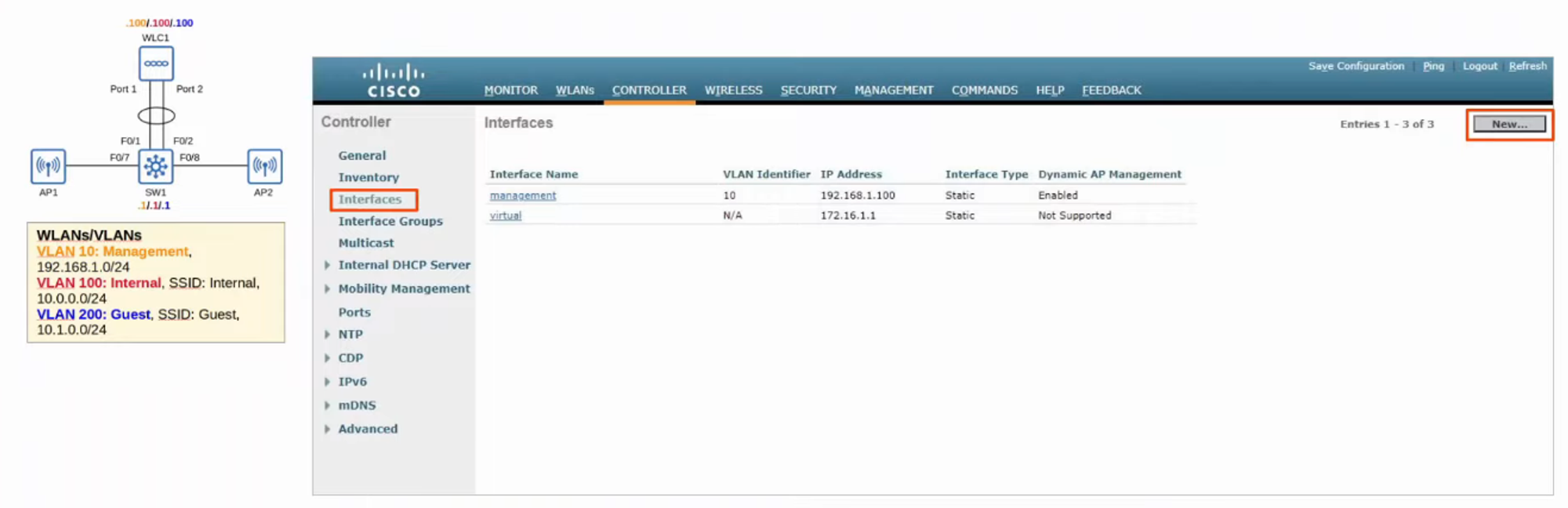
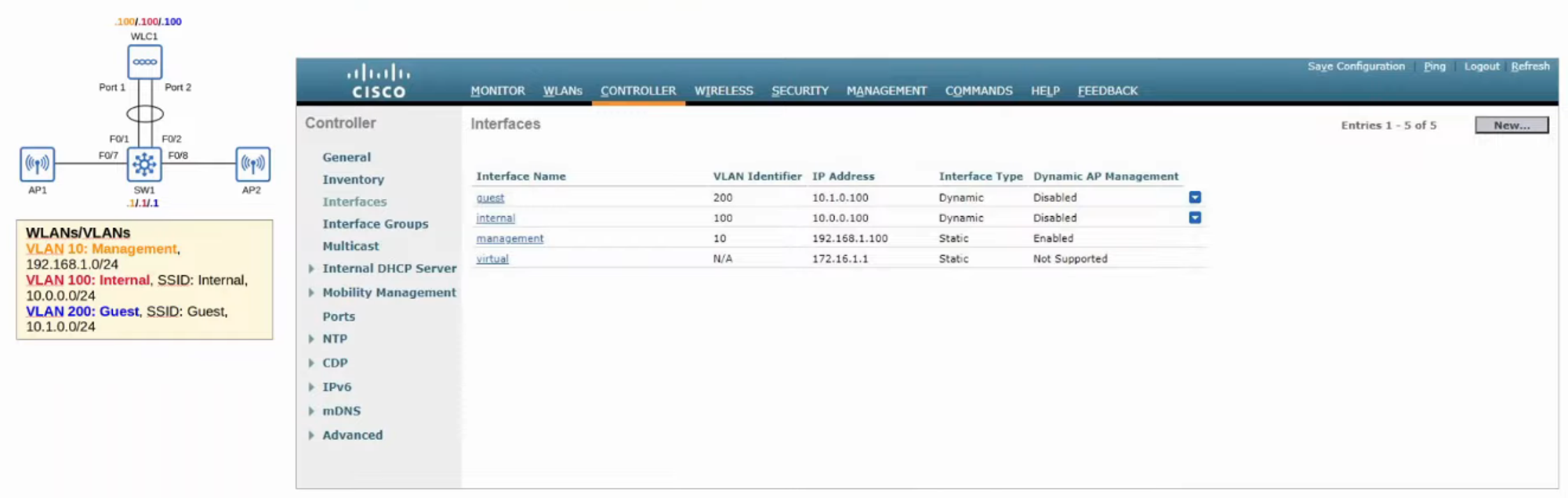
WLC INTERFACES
-
MANAGEMENT INTERFACES
- Used for management traffic such as TELNET, SSH, HTTP, HTTPS, RADIUS authentication, NTP, SYSLOG, etc.
- CAPWAP TUNNELS are also formed to / from the WLC’s management INTERFACE
-
REDUNDANCY MANAGEMENT INTERFACE
- When TWO WLCs are connected by their REDUNDANCY PORTS, one WLC is “ACTIVE” and the other is “STANDBY”
- This INTERFACE can be used to connect to and manage the “STANDBY” WLC
-
VIRTUAL INTERFACE
- This INTERFACE is used when communicating with WIRELESS CLIENTS to relay DHCP requests, perform CLIENT WEB AUTHENTICATION, etc.
-
SERVICE PORT INTERFACE
- If the SERVICE PORT is used, this INTERFACE is bound to it and used for OUT-OF-BAND MANAGEMENT
-
DYNAMIC INTERFACE
- These are the INTERFACES used to map a WLAN to a VLAN
- For example :
- TRAFFIC from the “INTERNAL” WLAN will be sent to the WIRED NETWORK from the WLCs “INTERNAL” DYNAMIC INTERFACE
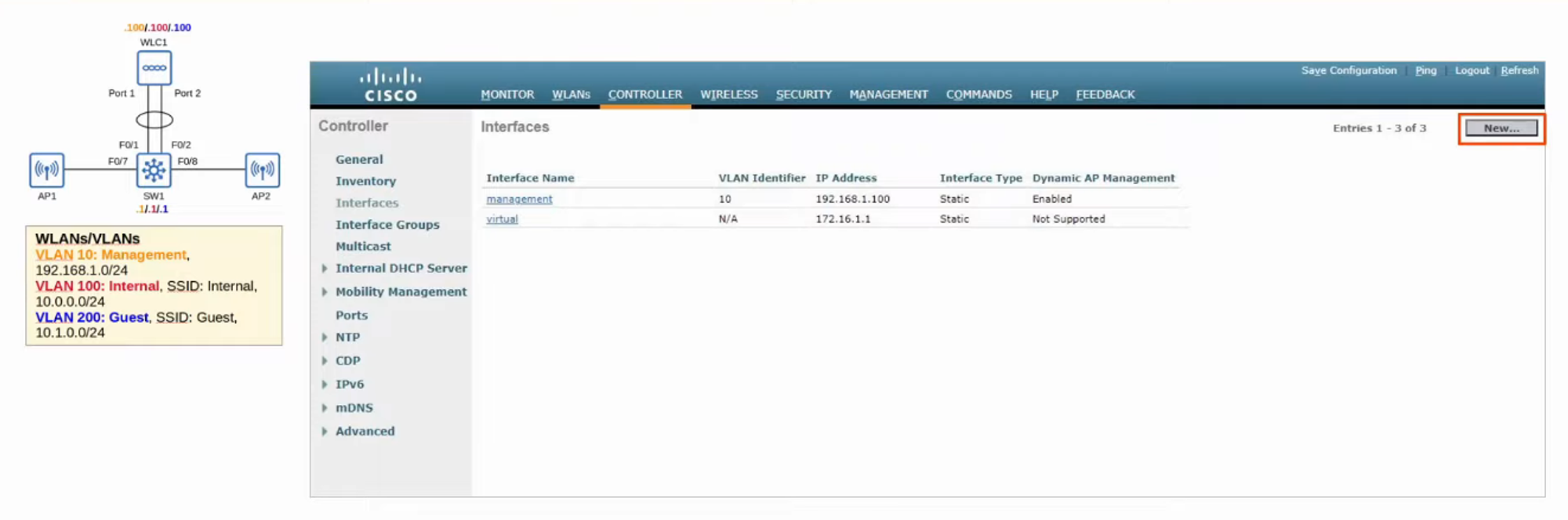
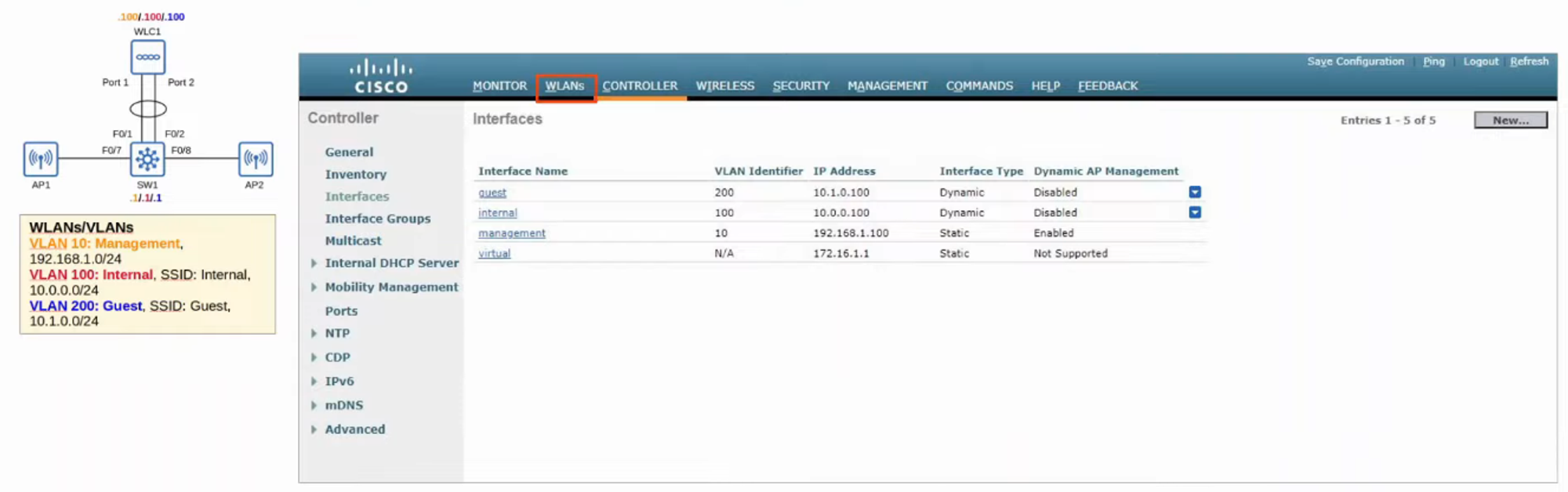
WLAN CONFIGURATION
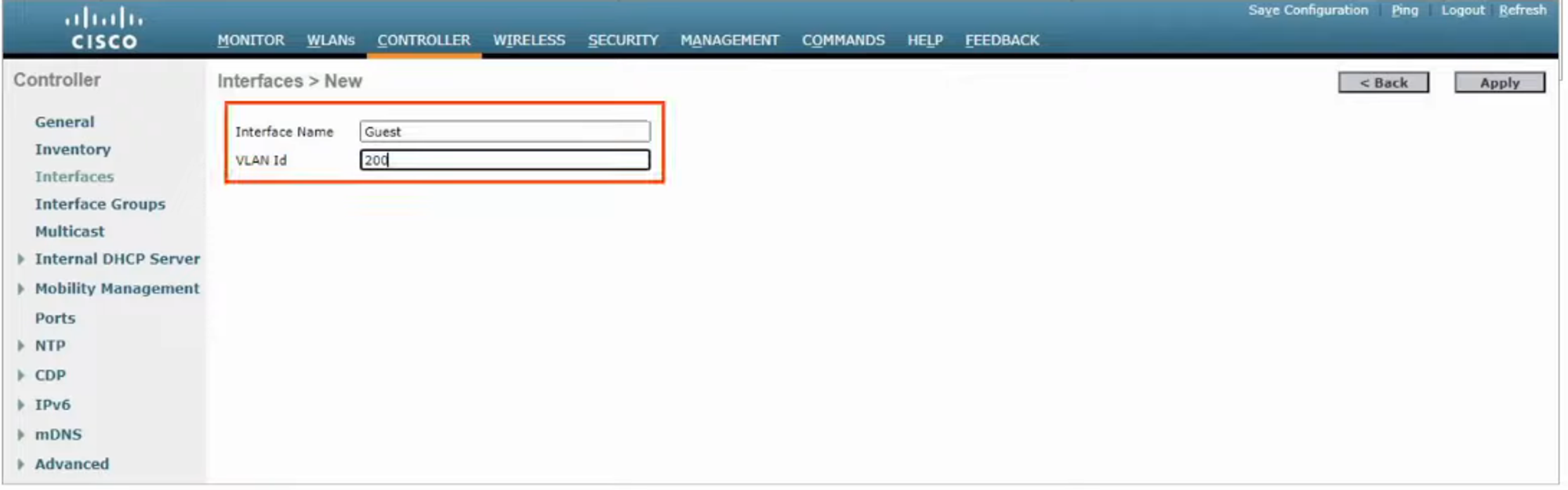
Click “NEW”
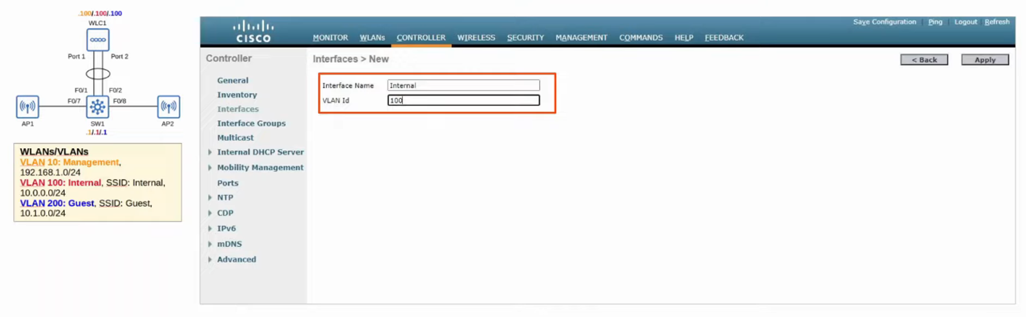
Fill in details of the interface and click “APPLY”
Fill out details (IP, Netmask, Gateway…) and then click “APPLY”
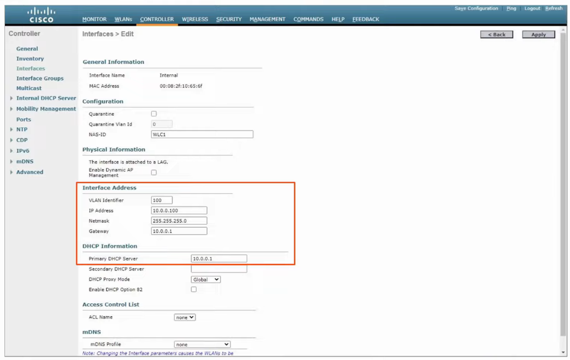
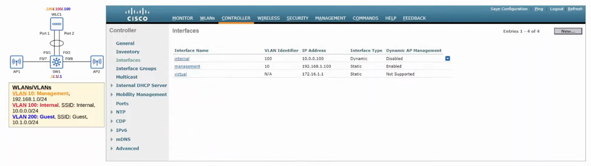
INTERNAL interface has now been created
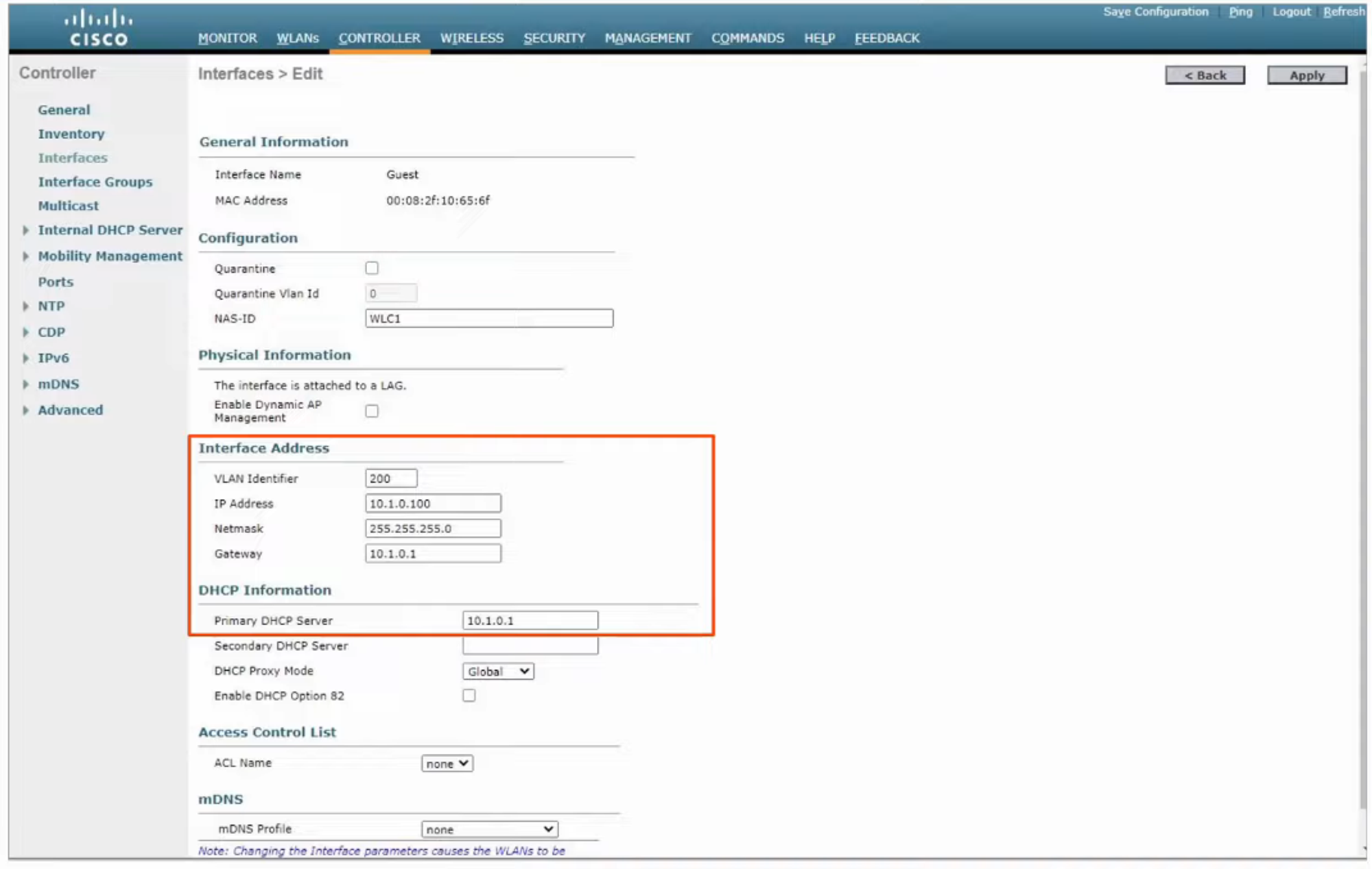
Now, repeat the above steps for the GUEST interface
Fill out details (IP, Netmask, Gateway…) and then click “APPLY”
Now that all the INTERFACES are created, we can start WLAN CONFIGURATION
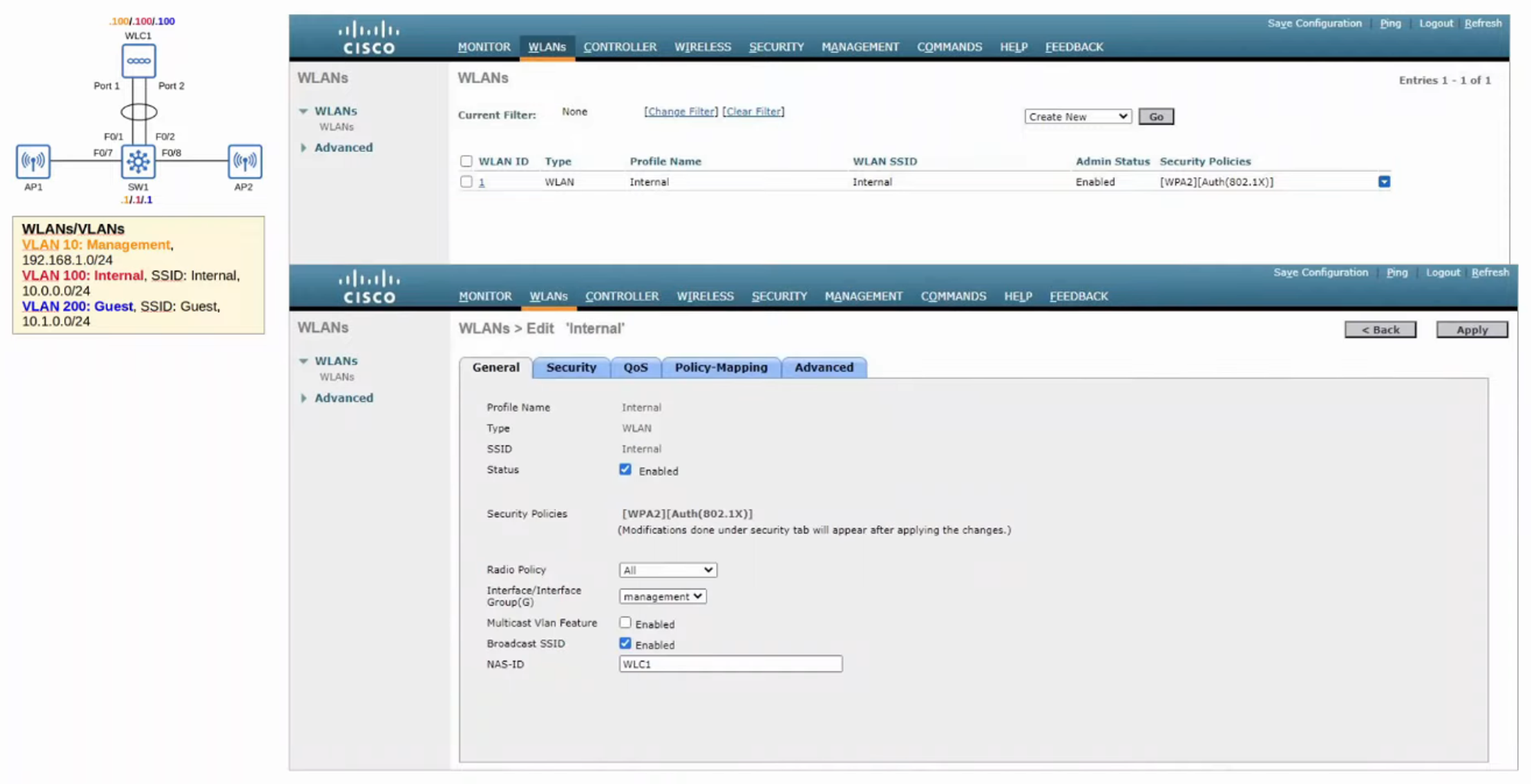
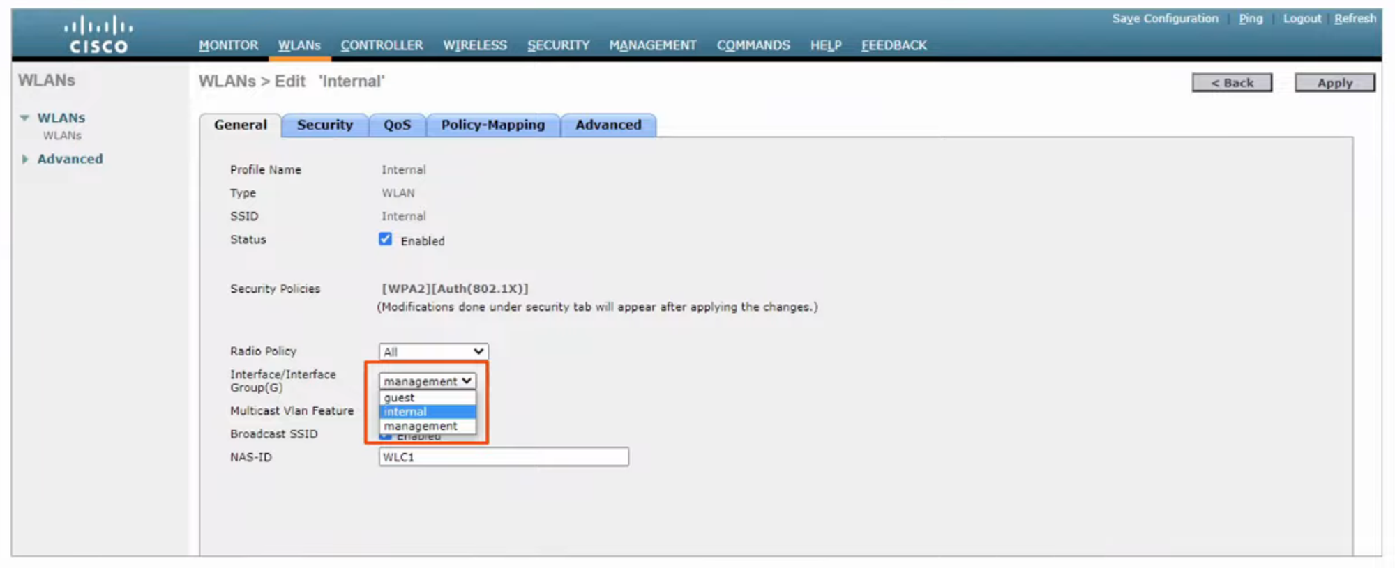
INTERNAL WLAN is set to “MANAGEMENT”; it needs to be changed to “INTERNAL”
SECURITY will also need to be changed from [WPA2] to [WPA2 PSK]
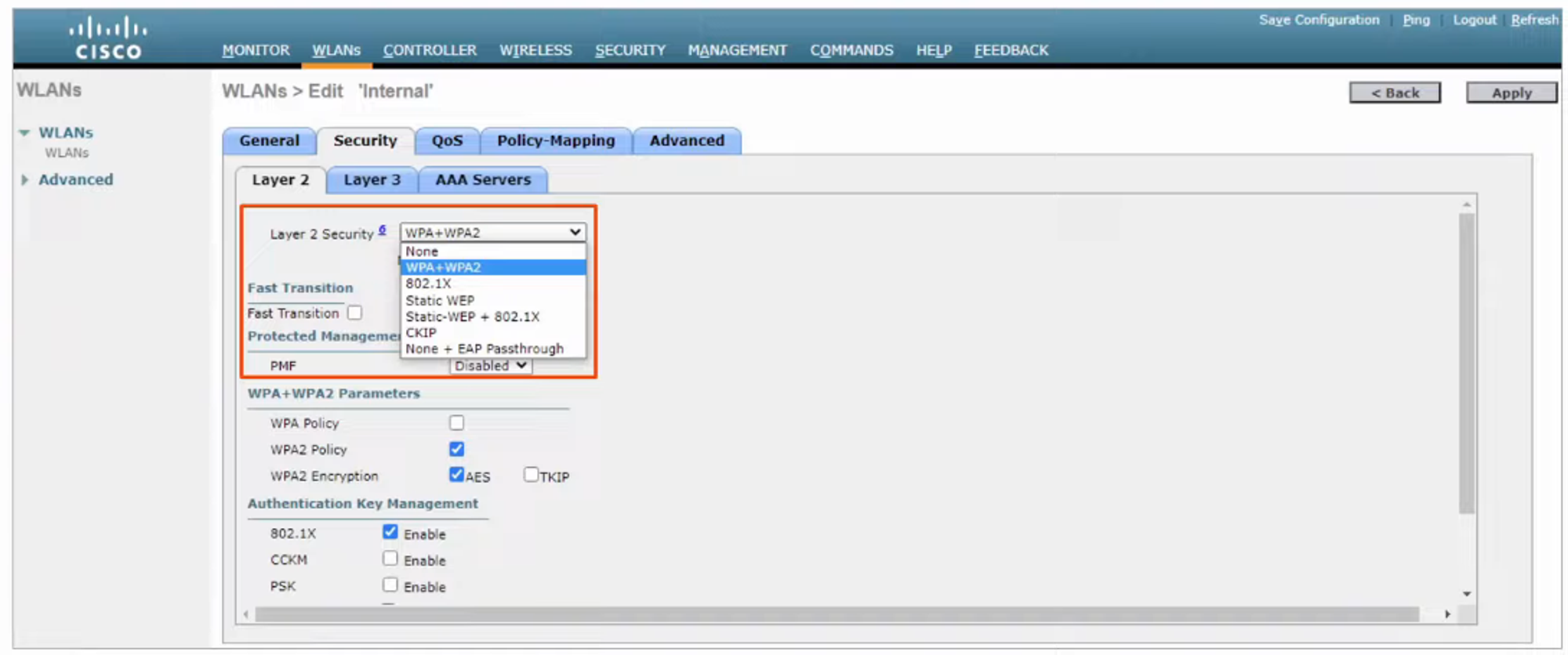
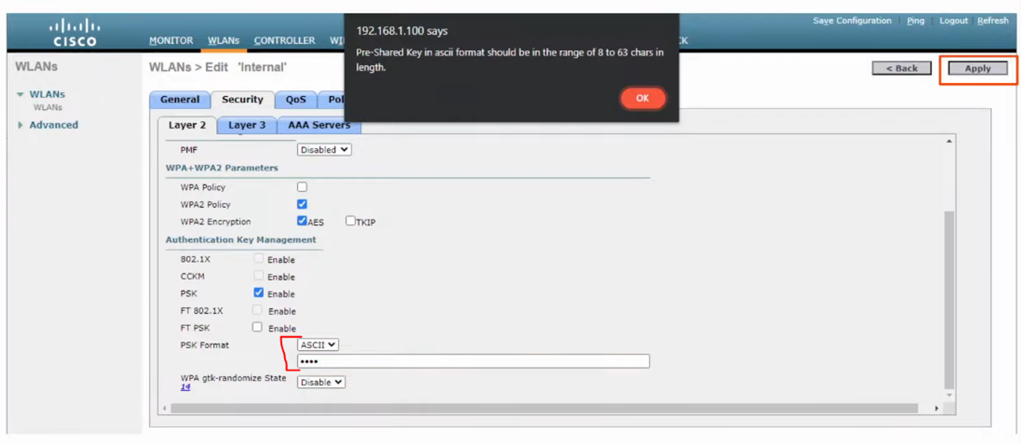
(Need to CHECK the PSK “Enable” box at the bottom)
Change the PSK FORMAT to “ASCII” and enter a PASSWORD (at least 8 chars in length)
-
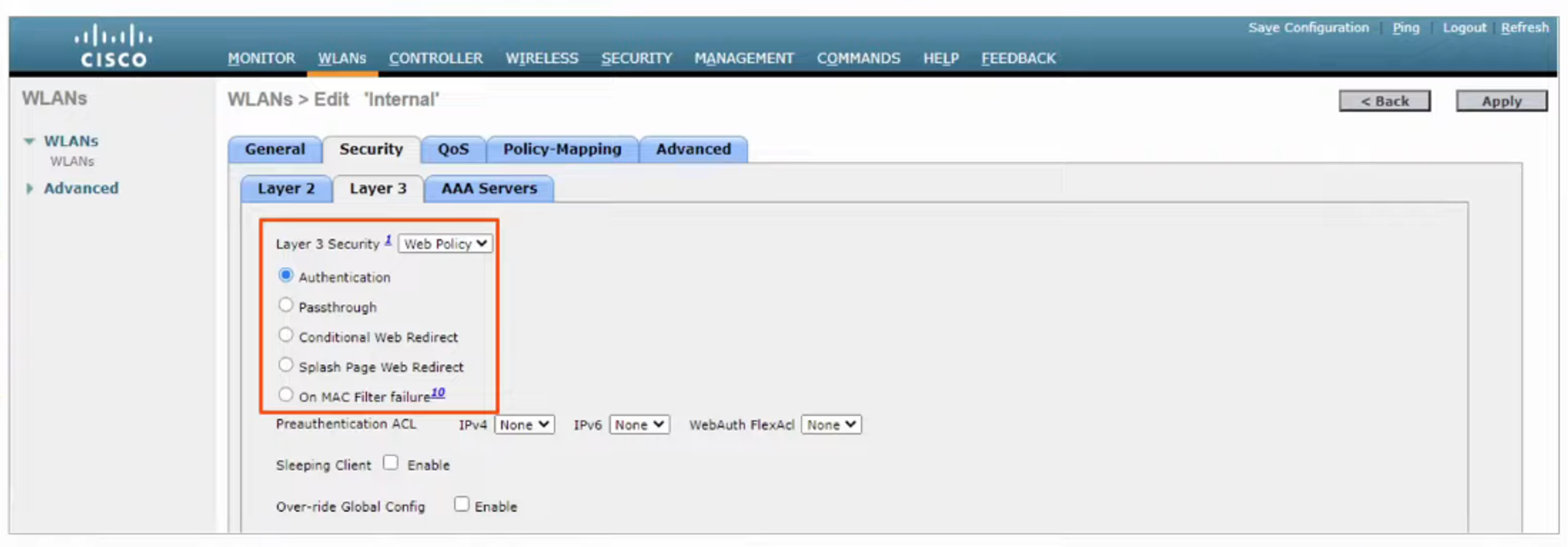
WEB AUTHENTICATION
- After the WIRELESS CLIENTS get an IP ADDRESS and try to access a WEB PAGE, they will have to enter a USERNAME and PASSWORD to AUTHENTICATE.
-
WEB PASSTHROUGH
- Similar to the above, but NO USERNAME or PASSWORD are required.
- A warning or statement is displayed, and the CLIENT simply has to agree to gain access to the INTERNET.
-
CONDITIONAL and SPLASH PAGE web redirect options are similar but additionally require 802.1x LAYER 2 AUTHENTICATION.
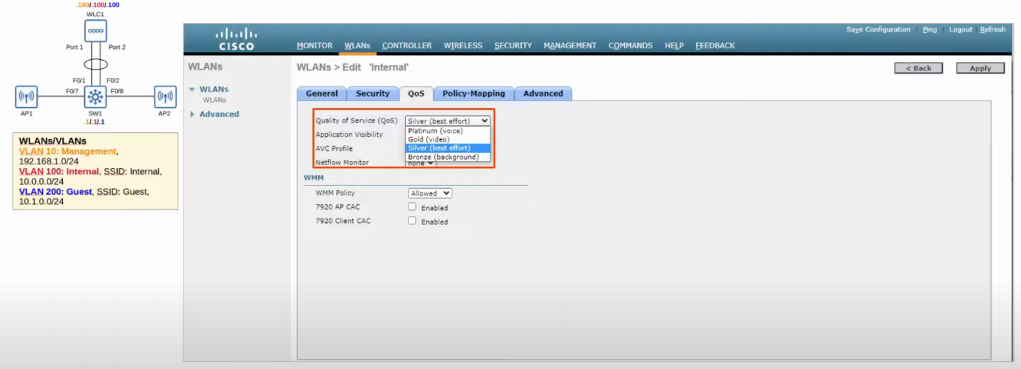
QoS
- Default QoS setting is “SILVER” (Best Effort). This can be changed depending on the class of traffic being sent through the WLAN.
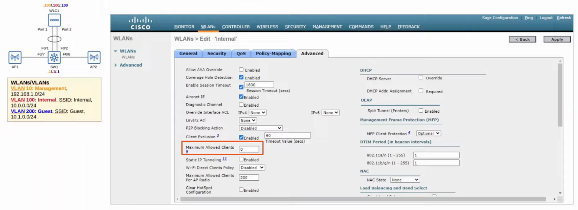
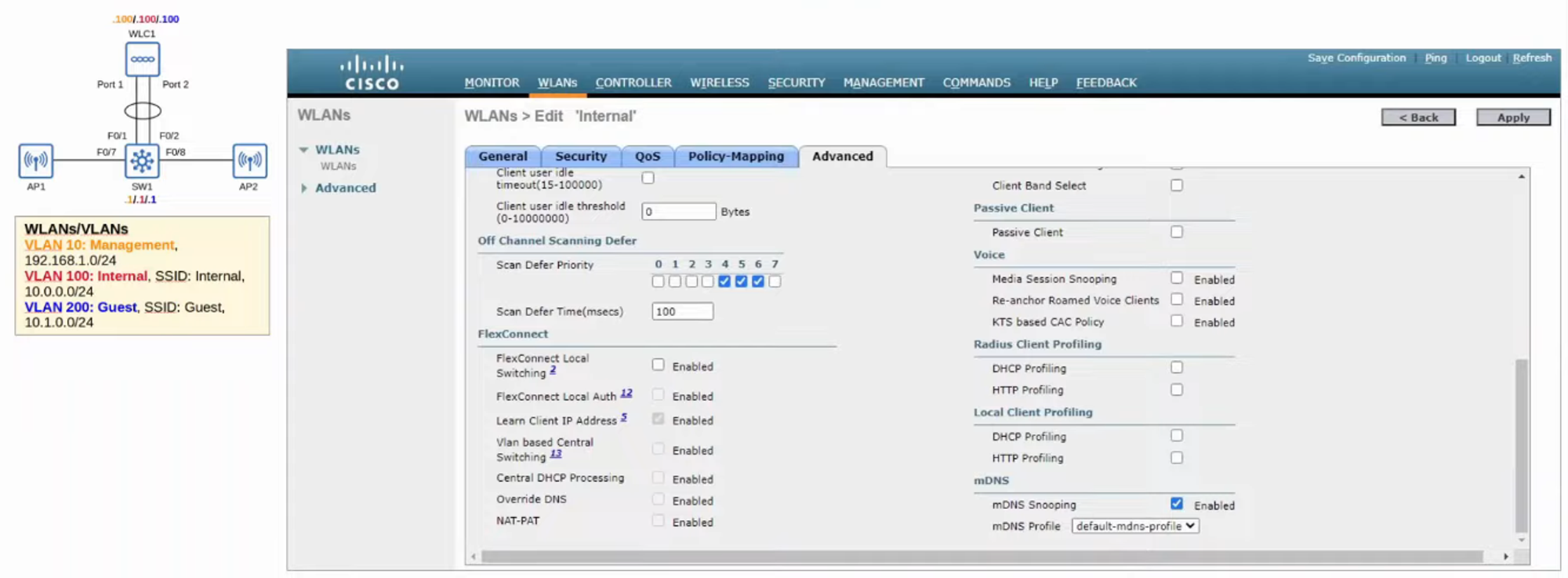
ADVANCED SETTINGS
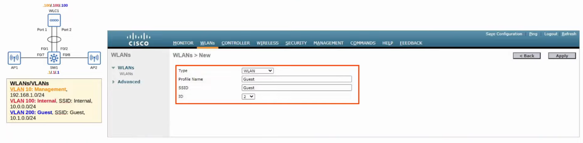
CONFIGURING A NEW WLAN (GUEST)
- Change STATUS to “ENABLED” and INTERFACE GROUP to “GUEST”.
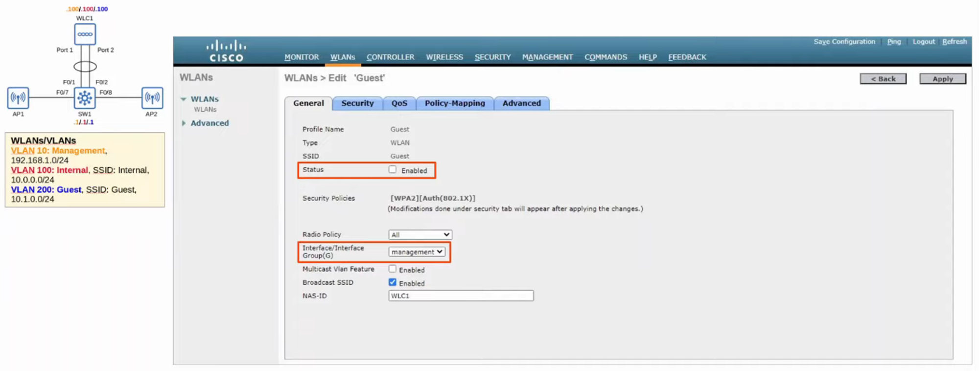
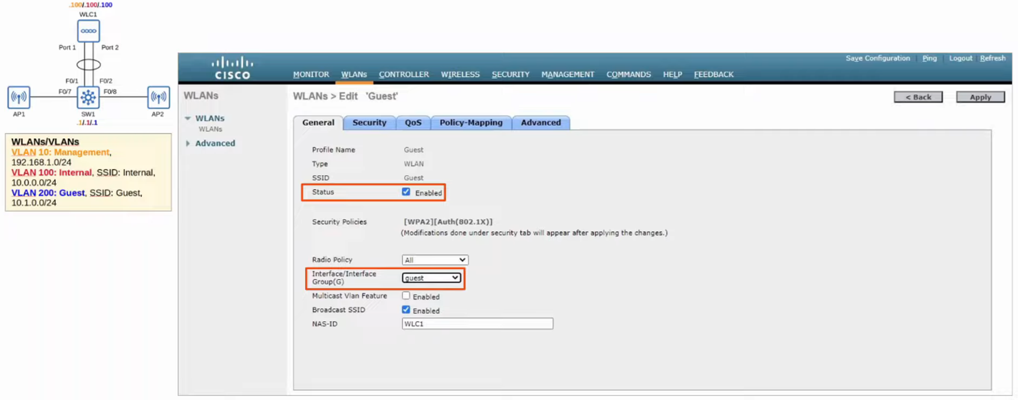
- Now, we need to change the SECURITY POLICY to [WPA2][Auth(PSK)].
Returning to MONITORING, we can see the changes we made to the CONFIGURATION.
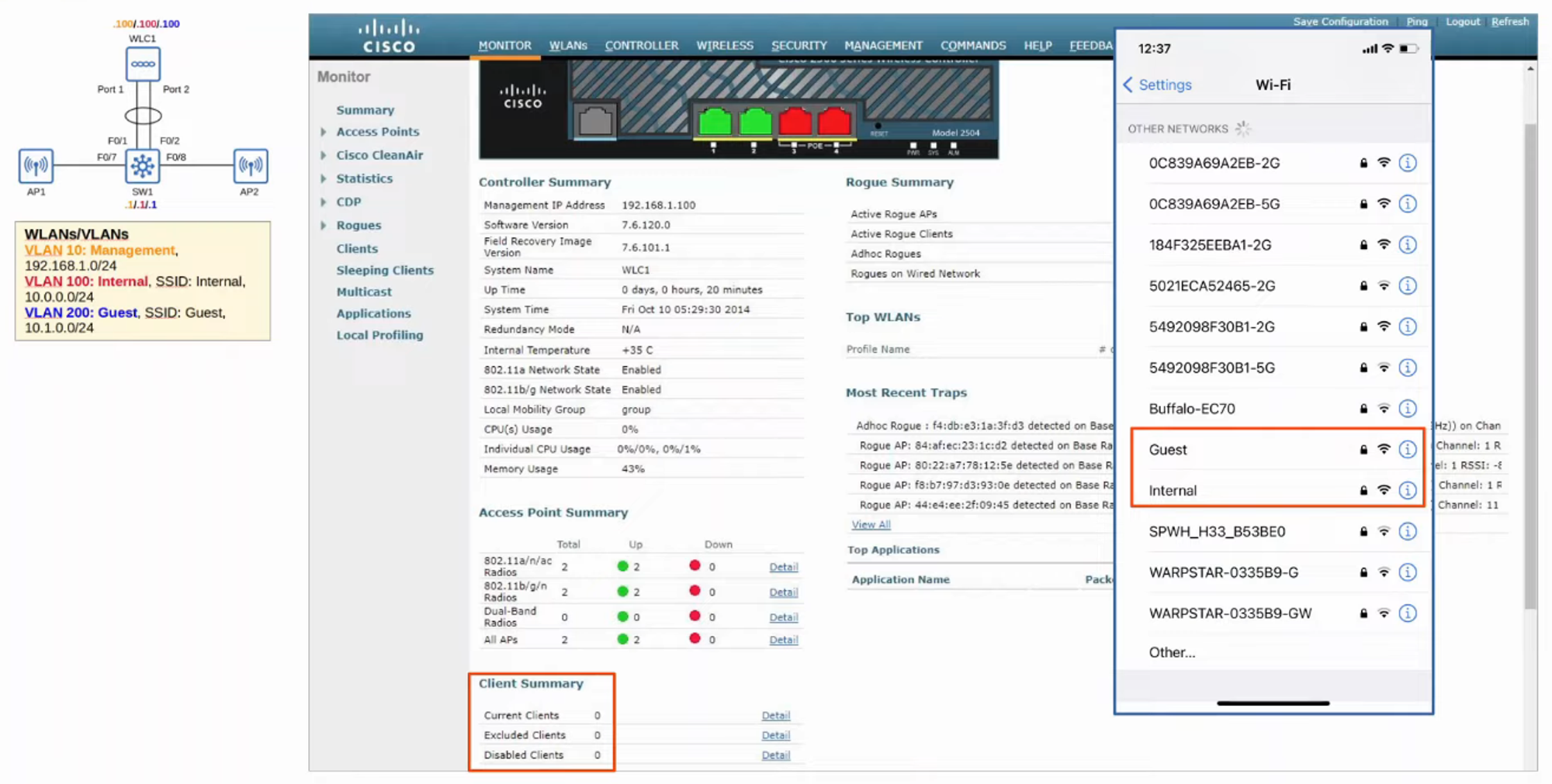
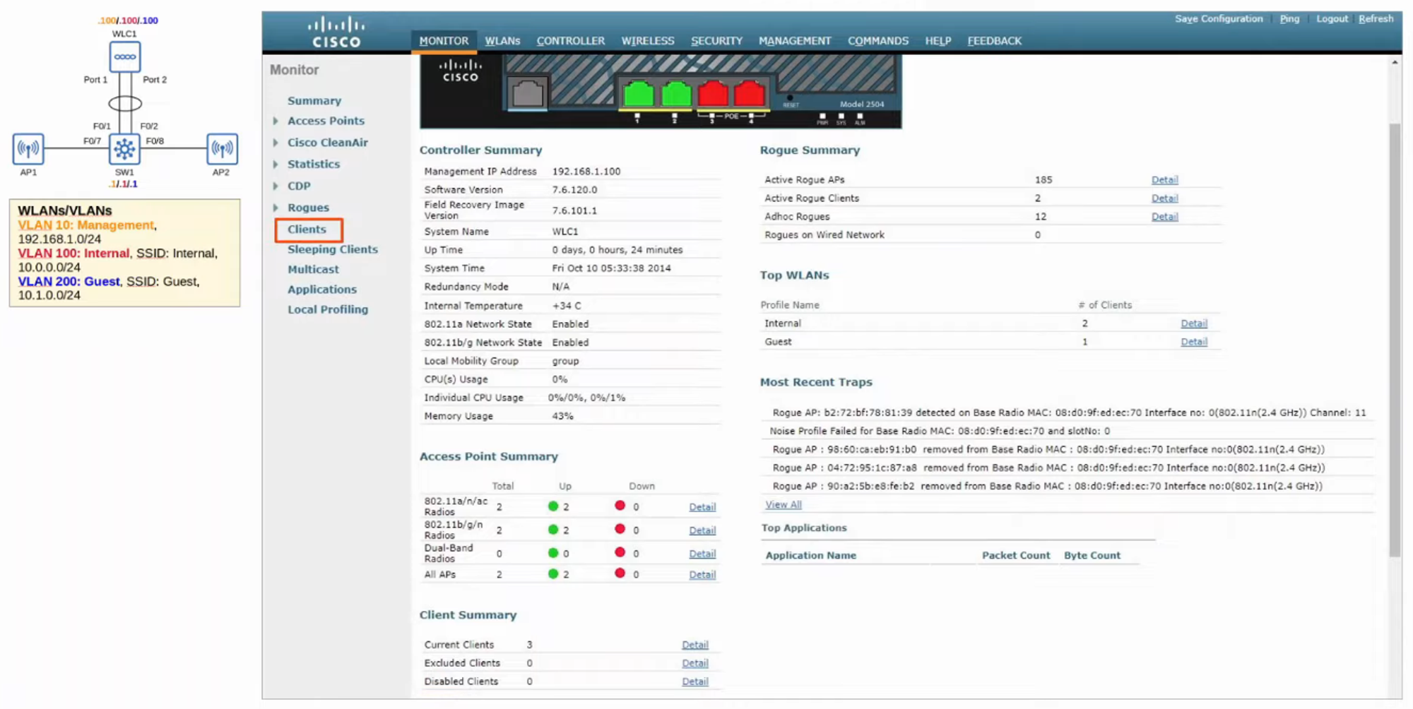
- The current number of CLIENTS is now 0. By connecting to the WLANS, these numbers should change.
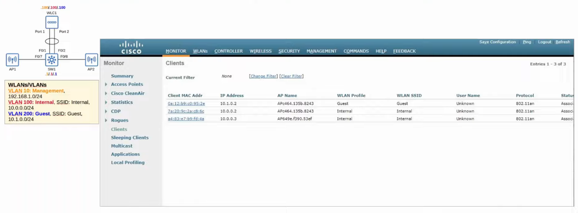
- To SEE a list of the CLIENTS connected, click the left-hand side “CLIENTS” tab.
ADDITIONAL WLC FEATURES
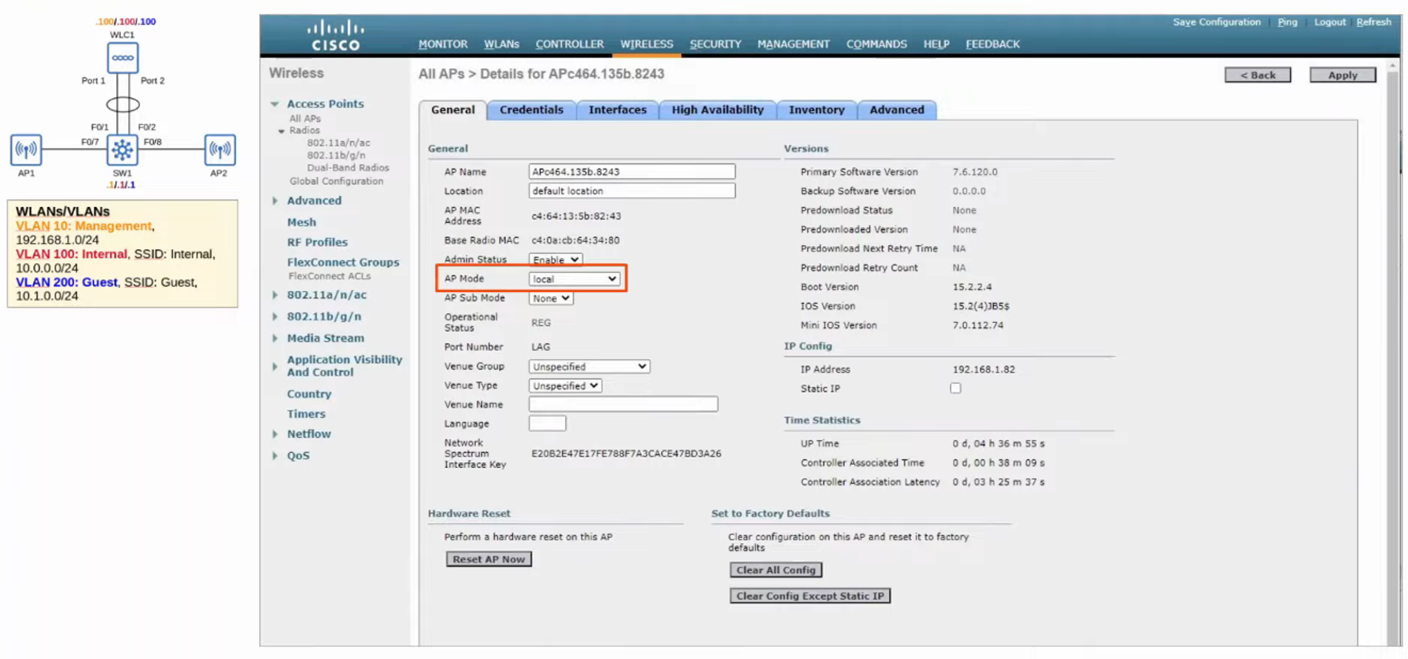
- WIRELESS tab showing a list of the APs currently in the NETWORK.
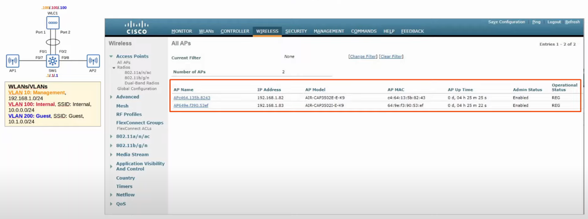
- Clicking on an AP shows information and configuration settings for it.
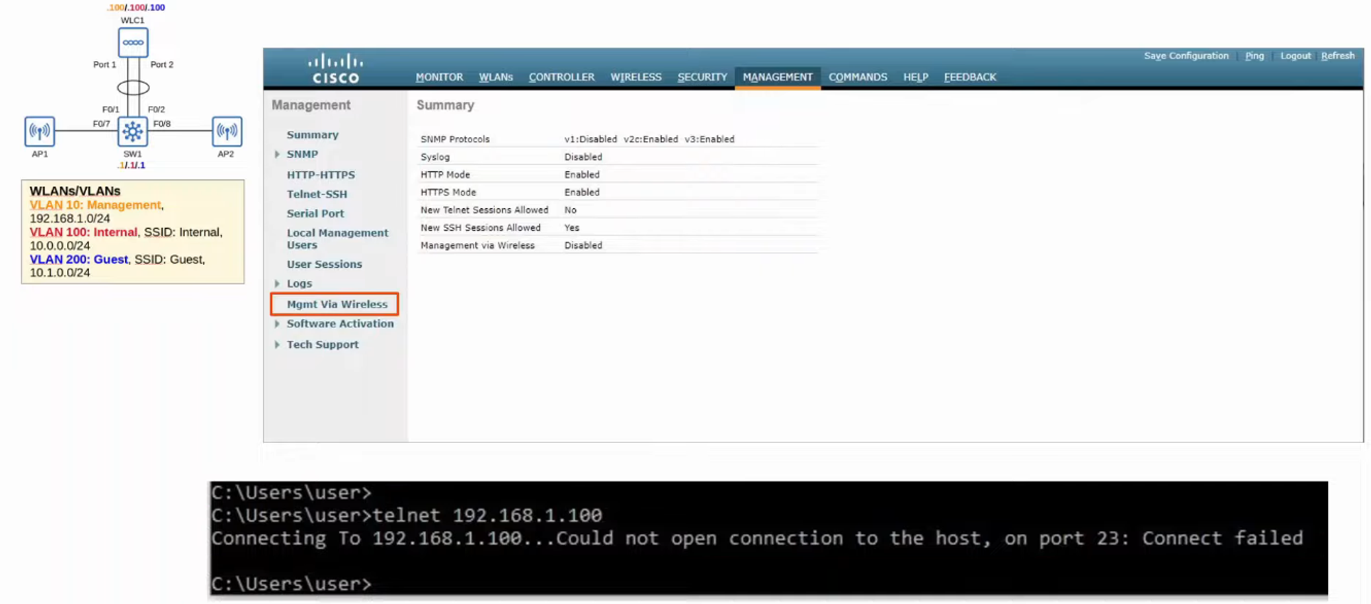
MANAGEMENT
- The MANAGEMENT tab allows you to change the ways you can MANAGE the WLC.
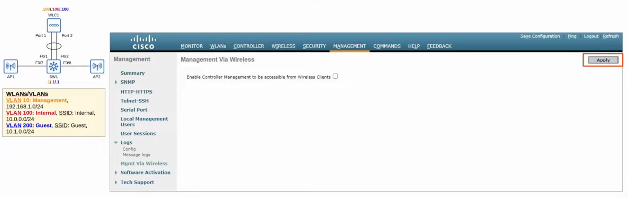
- Clicking “Mgmt Via Wireless” allows you to change if you can access MANAGEMENT via WI-FI.
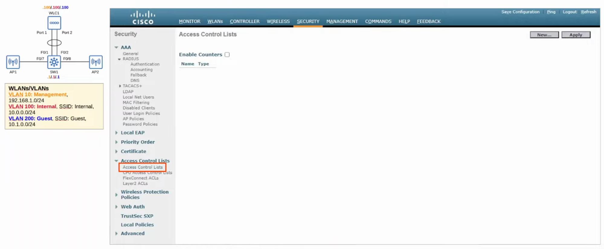
SECURITY
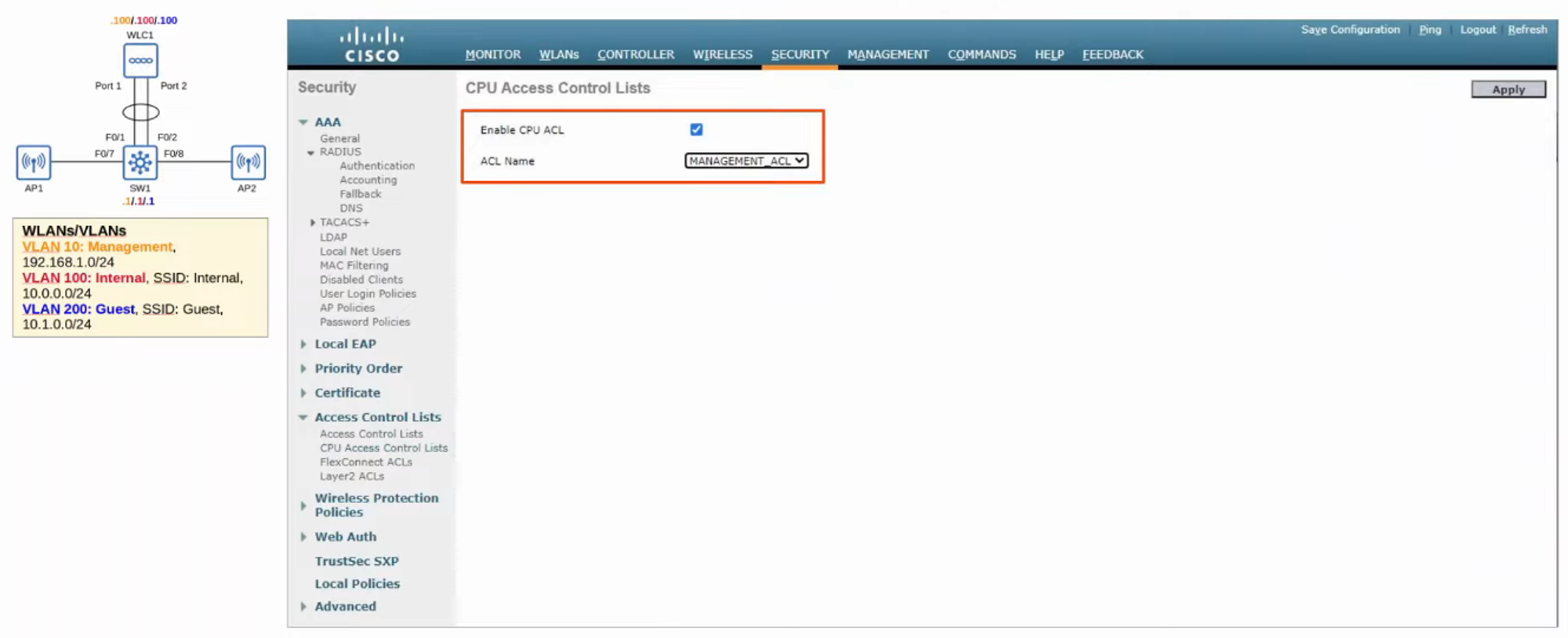
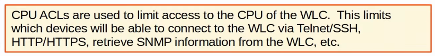
- The SECURITY tab can allow us to create ACCESS LISTS.
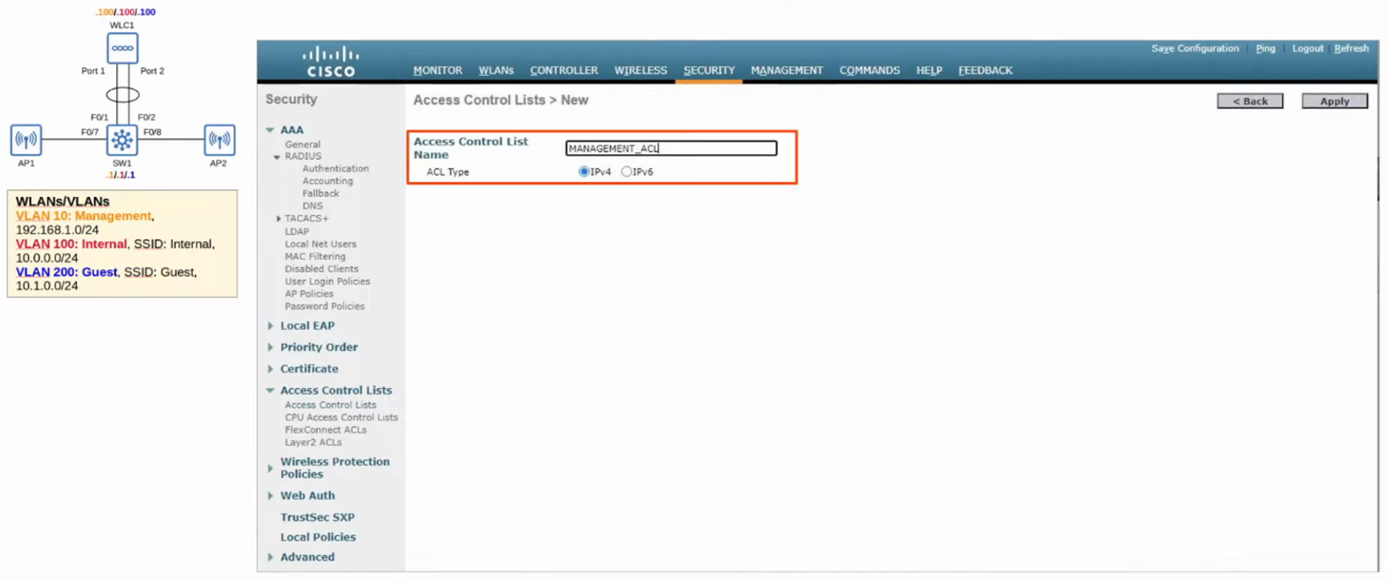
- NAME the ACL and define what kind of IP ADDRESS it’s for.
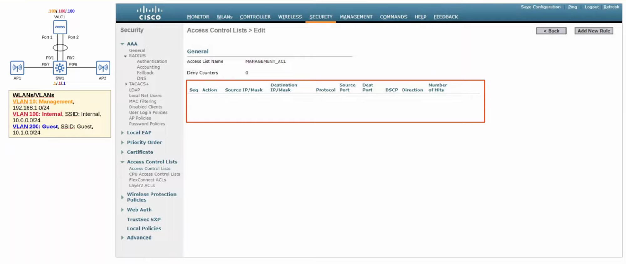
- CLICK “Add New Rule” to specify the ACL Rules (What traffic can pass).
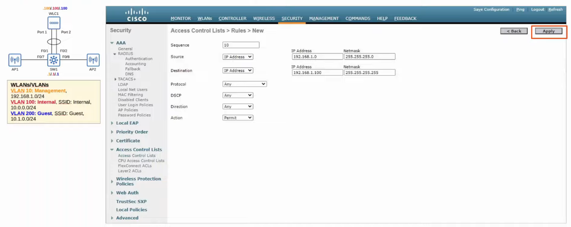
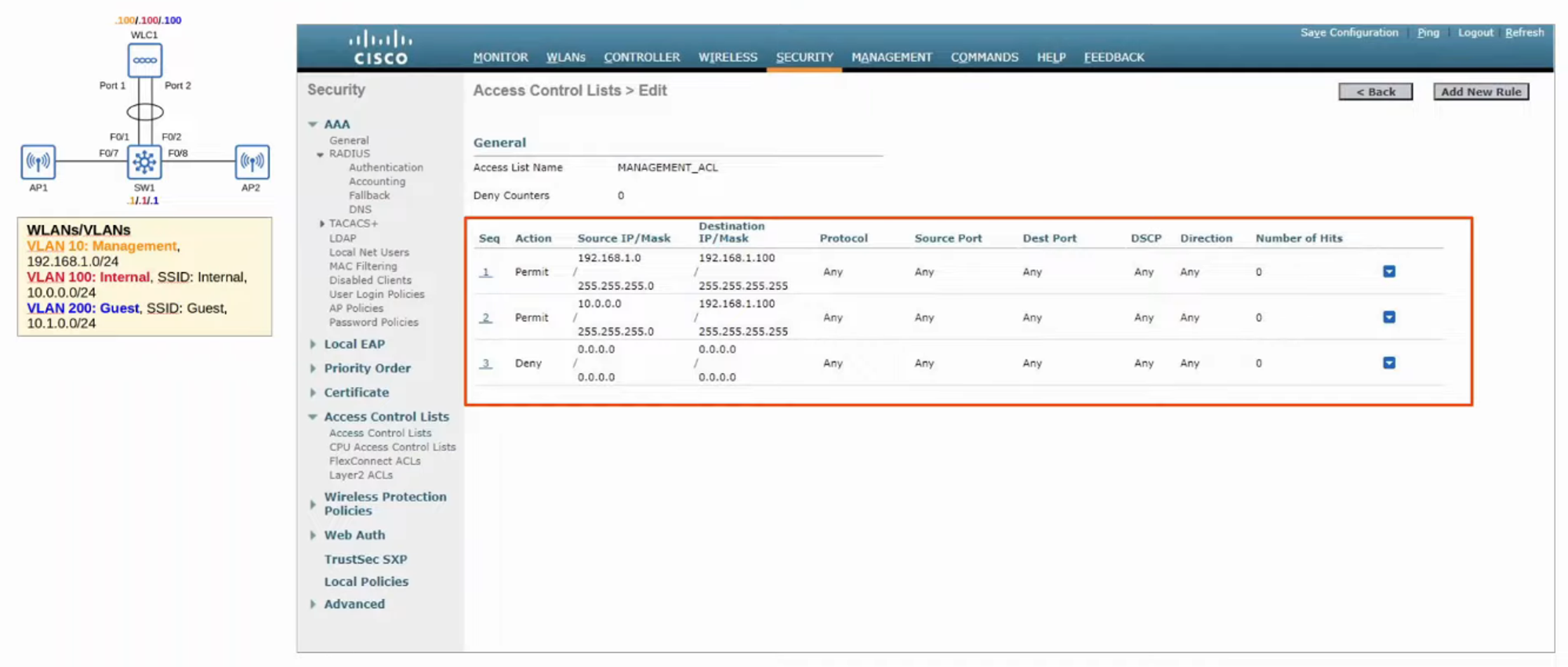
- Now we need to APPLY the ACL (just like applying it to an INTERFACE on a ROUTER).
- Click “CPU ACL” from the left-hand menu.
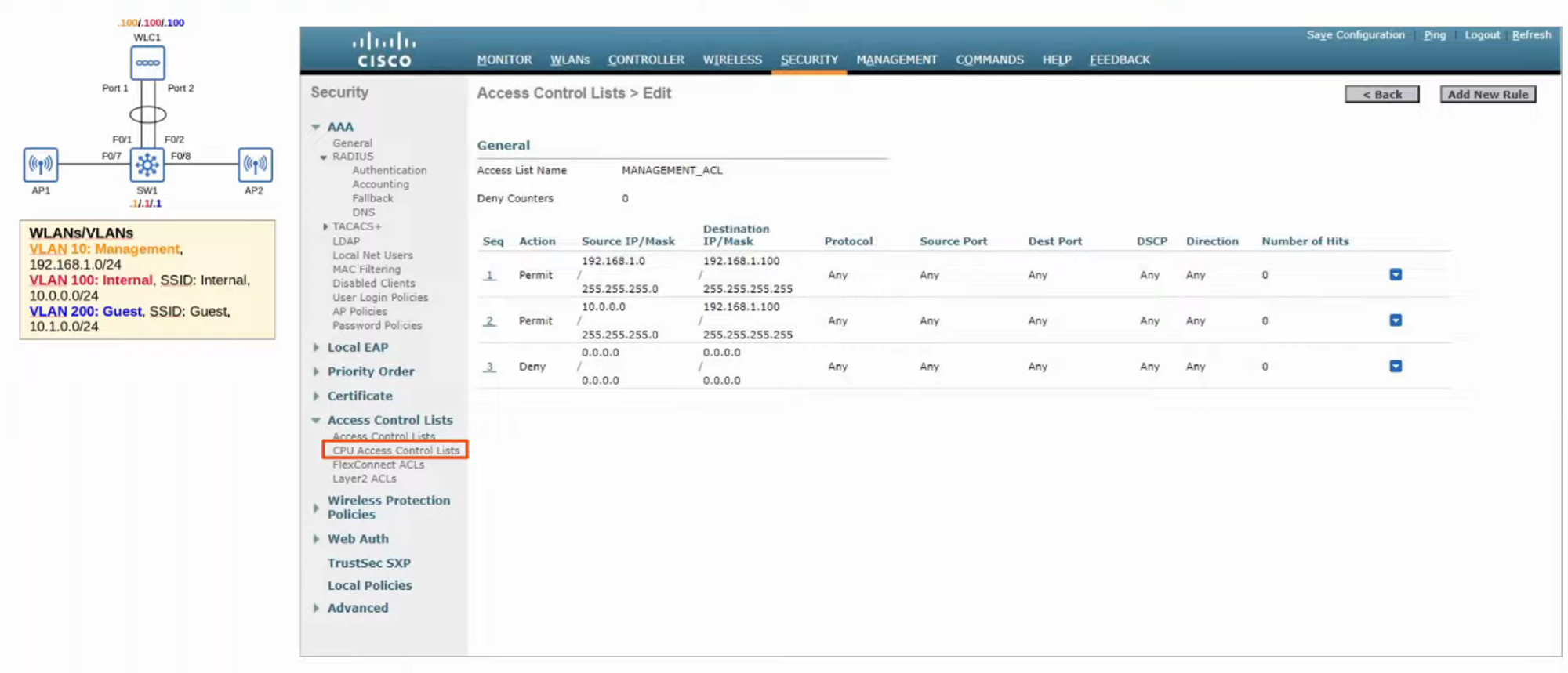
- Select the new ACL from the pull-down list and then click “APPLY.”