Introduction to WANs
- WAN stands for Wide Area Network.
- A WAN is a network that extends over a large geographic area and is used to connect geographically separate Local Area Networks (LANs).
- While the Internet can be considered a WAN, the term “WAN” typically refers to an enterprise’s private connections that link their offices, data centers, and other sites.
- Virtual Private Networks (VPNs) can create private WAN connections over public/shared networks like the Internet.
- Numerous WAN technologies have emerged over the years. The availability of these technologies can vary by location, and some may be considered legacy (outdated) in one country but still in use in others.
WAN Connection Types
WAN Over Dedicated Connection (Leased Line)
-
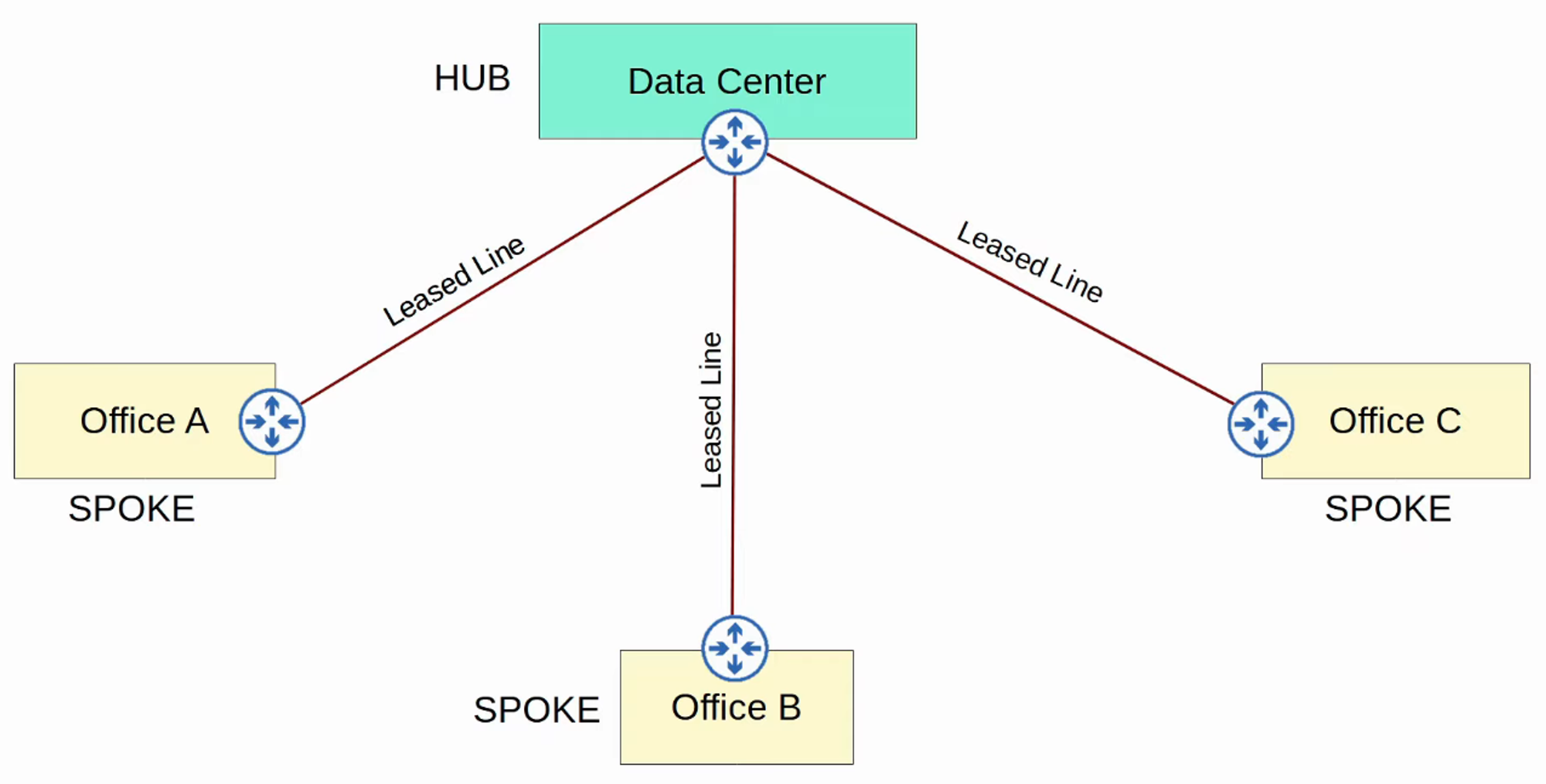
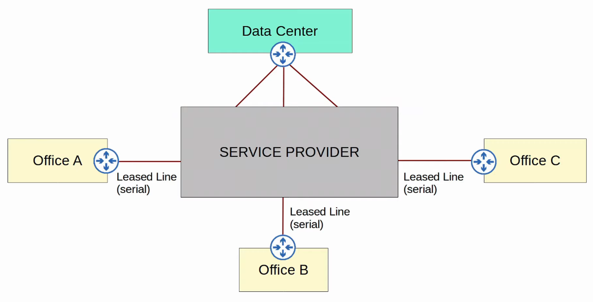
Hub-and-Spoke Topology
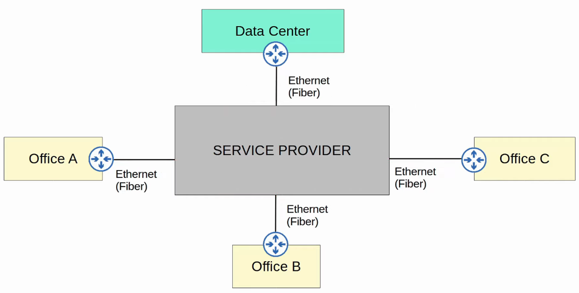
WAN Connection via Ethernet (Fiber)
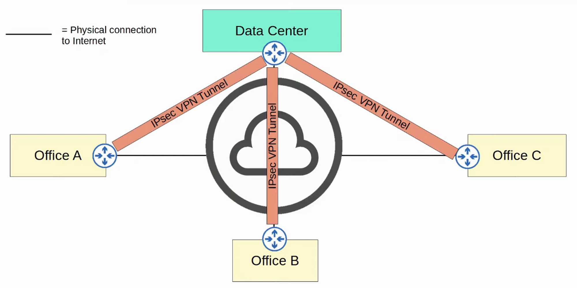
WAN Over Shared Infrastructure (Internet VPN)
Leased Lines
-
A leased line is a dedicated physical link that typically connects two sites.
-
Leased lines use serial connections (PPP or HDLC encapsulation).
-
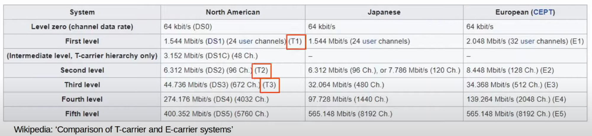
Various standards provide different speeds, and their availability can differ by country.
-
Due to their higher cost, longer installation lead times, and often slower speeds, leased lines are becoming less popular compared to Ethernet WAN technologies.
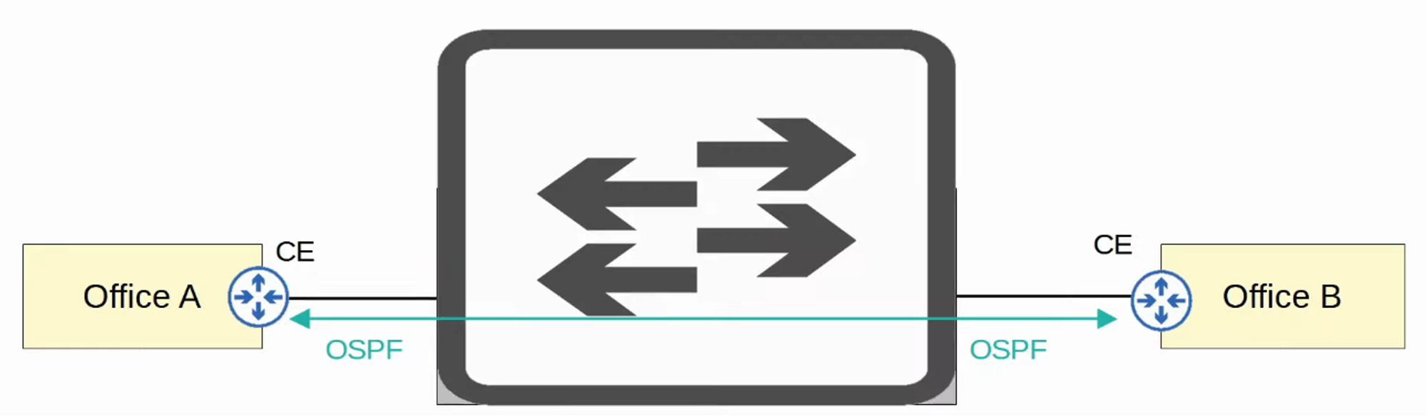
MPLS VPNs
- MPLS stands for Multi-Protocol Label Switching.
- Service providers’ MPLS networks share infrastructure, allowing multiple customer enterprises to connect and share the same infrastructure for WAN connections.
- The label switching in MPLS allows for the creation of VPNs over the MPLS infrastructure using labels.
Important Terms:
-
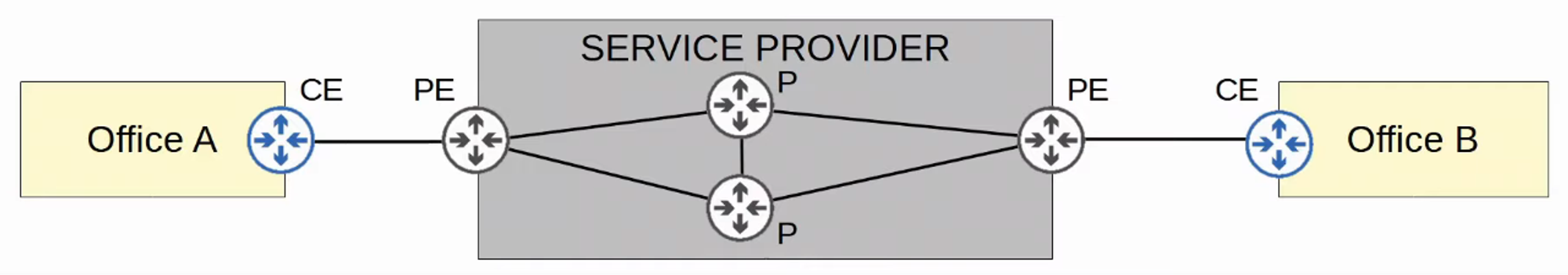
CE Router: Customer Edge Router
-
PE Router: Provider Edge Router
-
P Router: Provider Core Router
-
When PE routers receive frames from CE routers, they add a label to the frame. These labels are used for forwarding decisions within the service provider network, not based on the destination IP.
-
CE routers do not utilize MPLS; it is exclusively used by PE and P routers.
-
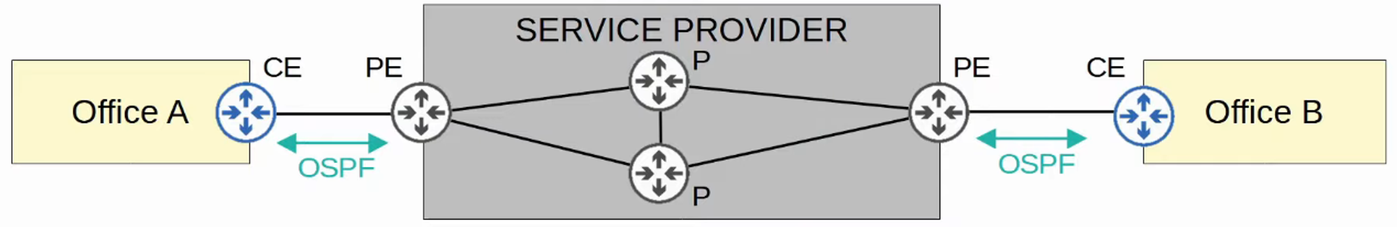
In a Layer 3 MPLS VPN, CE and PE routers peer using a routing protocol (e.g., OSPF) to share routing information.
Example:
-
Office A’s CE will peer with one PE.
-
Office B’s CE will peer with another PE.
-
Office A’s CE learns about Office B’s routes through OSPF peering, and vice versa.
-
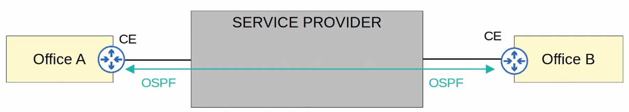
In a Layer 2 MPLS VPN, CE and PE routers do not form peerings. The service provider network is entirely transparent to the CE routers.
- It appears as if the two CE routers are directly connected; their WAN interfaces will be in the same subnet.
- If a routing protocol is used, the two CE routers will peer directly with each other.
MPLS Technologies
-
Various technologies can connect to a service provider’s MPLS network for WAN service.
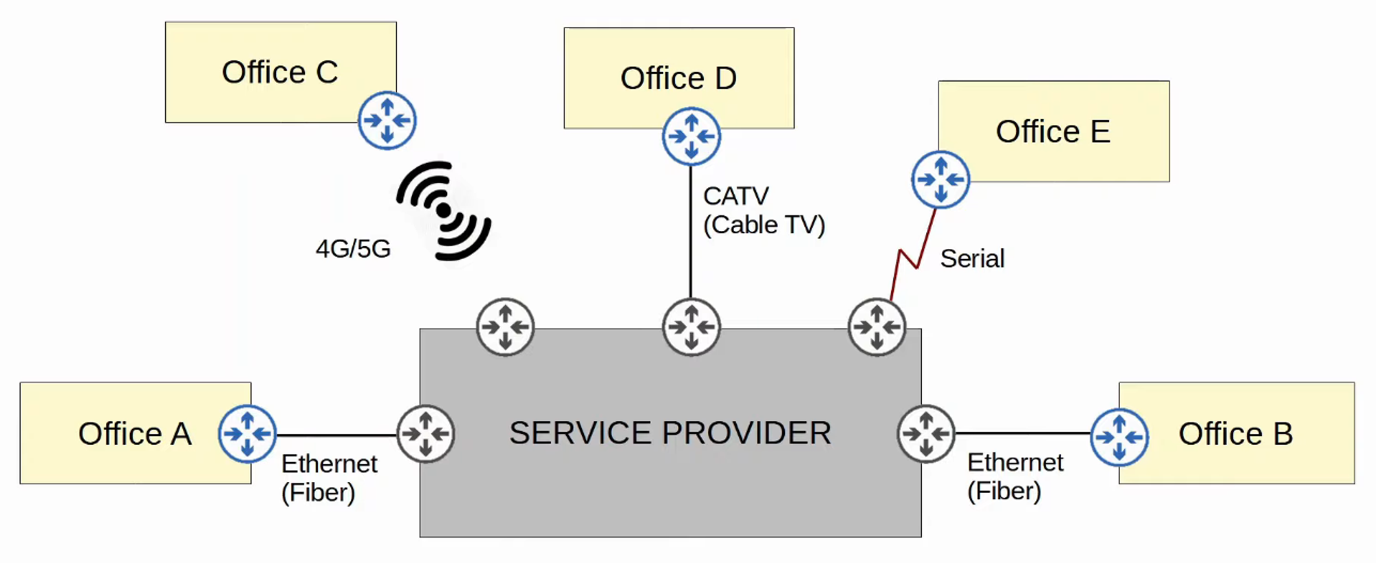
Internet Connectivity
- Enterprises can connect to the Internet through numerous methods. For example, private WAN technologies such as leased lines and MPLS VPNs can connect to a service provider’s Internet infrastructure.
- Additionally, technologies like CATV (Cable Television) and DSL (Digital Subscriber Line), commonly used for home internet access, can also be utilized by enterprises.
- Fiber optic Ethernet connections are increasingly popular for both enterprises and consumers due to the high speeds they provide over long distances.
Internet Access Technologies
-
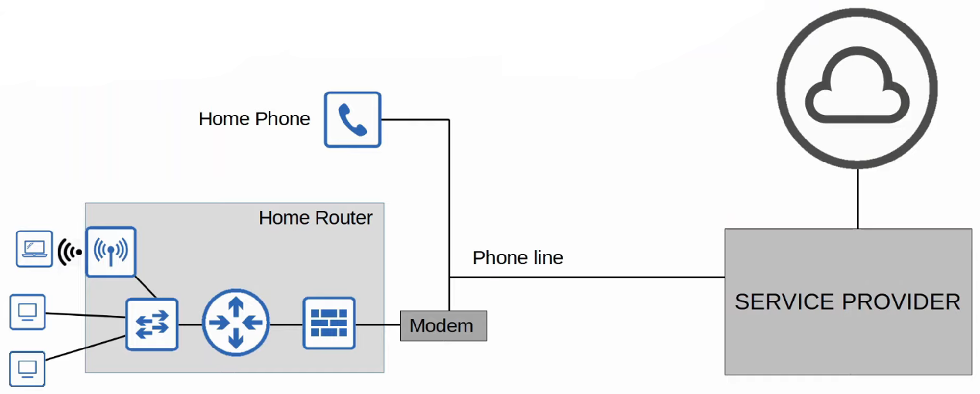
Digital Subscriber Line (DSL)
-
DSL provides Internet connectivity over phone lines, allowing customers to share the same line typically installed in most homes.
-
A DSL modem (Modulator/Demodulator) is required to convert data into a suitable format for transmission over phone lines. This modem may be a separate device or integrated into a home router.
-
-
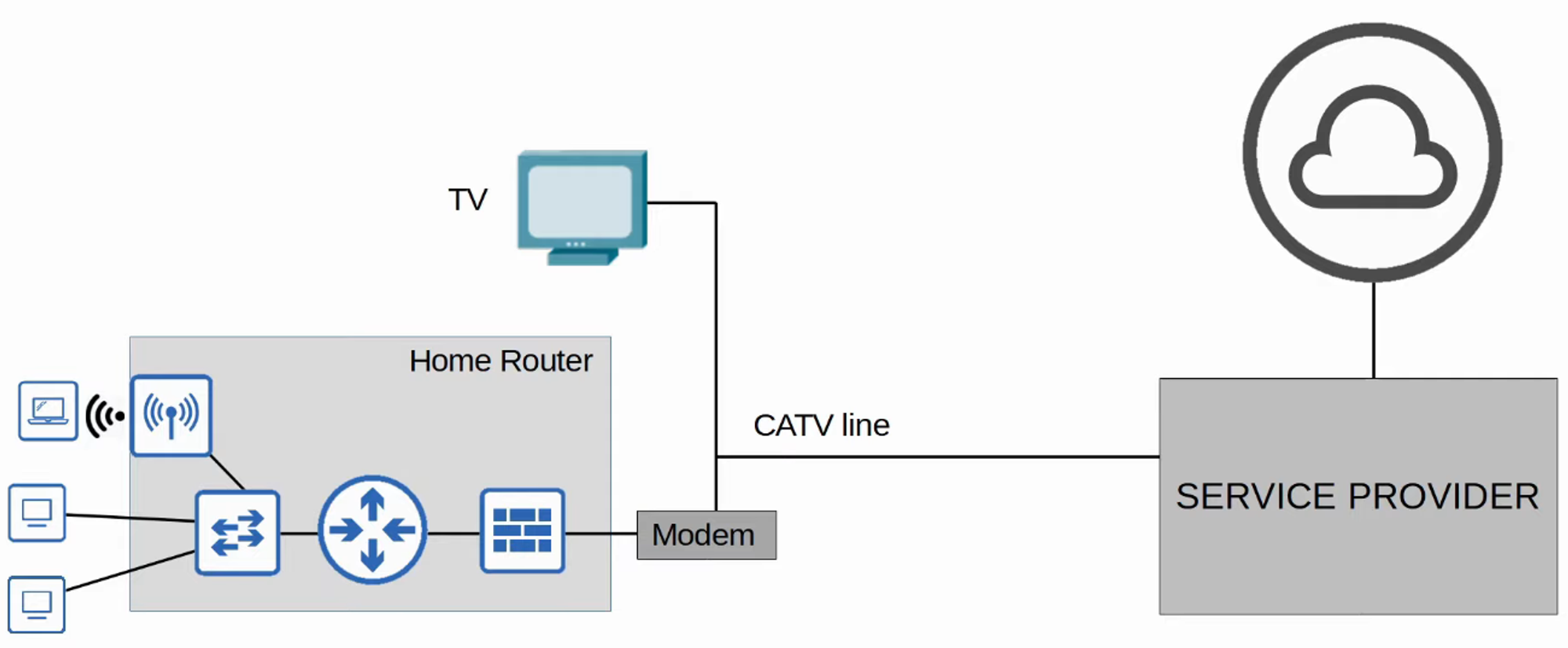
Cable Internet (CATV)
-
Cable Internet provides access via the same CATV lines used for television service.
-
Like DSL, a cable modem is necessary to convert data for transmission over CATV cables. This can also be a separate device or built into the home router.
-
Redundant Internet Connections
Internet VPNs
- Private WAN services such as leased lines and MPLS provide security by ensuring that each customer’s traffic is separated using dedicated physical connections or MPLS tags.
- When utilizing the Internet as a WAN to connect sites, there is no built-in security by default. To ensure secure communication over the Internet, VPNs (Virtual Private Networks) are implemented.
Types of Internet VPNs:
- Site-to-Site VPNs using IPSec
- Remote-Access VPNs using TLS
Site-to-Site VPNs (IPSec)
-
A site-to-site VPN establishes a VPN connection between two devices, connecting two sites over the Internet.
-
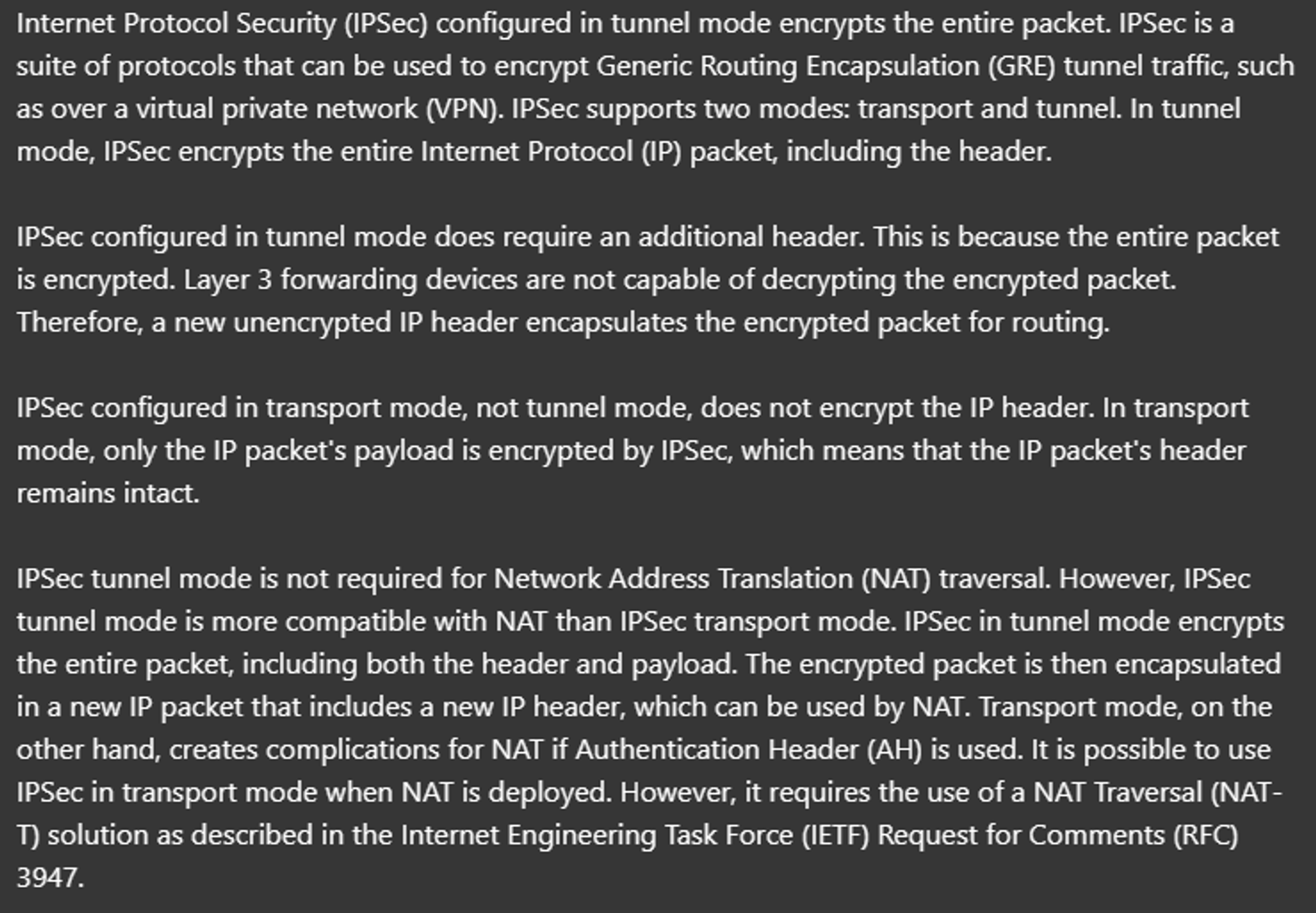
A VPN tunnel is created by encapsulating the original IP packet with a VPN header and a new IP header. When using IPSec, the original packet is encrypted before encapsulation.
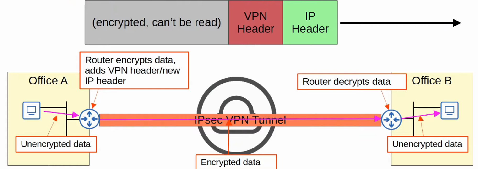
Process Summary:
- The sending device combines the original packet with a session key (encryption key) and processes them through an encryption formula.
- The sending device encapsulates the encrypted packet with a VPN header and a new IP header.
- The new packet is sent to the device on the opposite end of the tunnel.
- The receiving device decrypts the data to retrieve the original packet, forwarding it to its destination.
- In a site-to-site VPN, a tunnel is formed only between two tunnel endpoints (e.g., the two routers connected to the Internet).
- Other devices within each site do not need to create individual VPNs; they send unencrypted data to their site’s router, which encrypts it for transmission through the tunnel.
Limitations of Standard IPSec
- IPSec does not support broadcast or multicast traffic, only unicast.
- This limitation affects the use of routing protocols like OSPF, which rely on multicast traffic. A solution is to use GRE over IPSec.
- Configuring a full mesh of tunnels between many sites can be labor-intensive.
GRE over IPSec
-
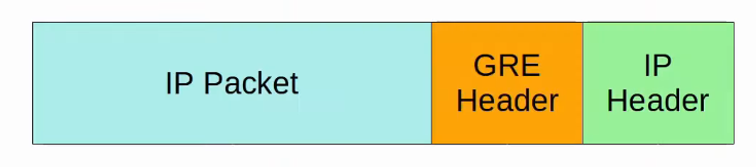
GRE (Generic Routing Encapsulation) creates tunnels like IPSec but does not encrypt the original packet, making it insecure.
-
However, GRE can encapsulate a wide variety of Layer 3 protocols, including broadcast and multicast messages.
-
To combine GRE’s flexibility with IPSec’s security, GRE over IPSec can be implemented. The original packet is encapsulated with a GRE header and a new IP header, and then the GRE packet is encrypted and encapsulated within an IPSec VPN header and a new IP header.

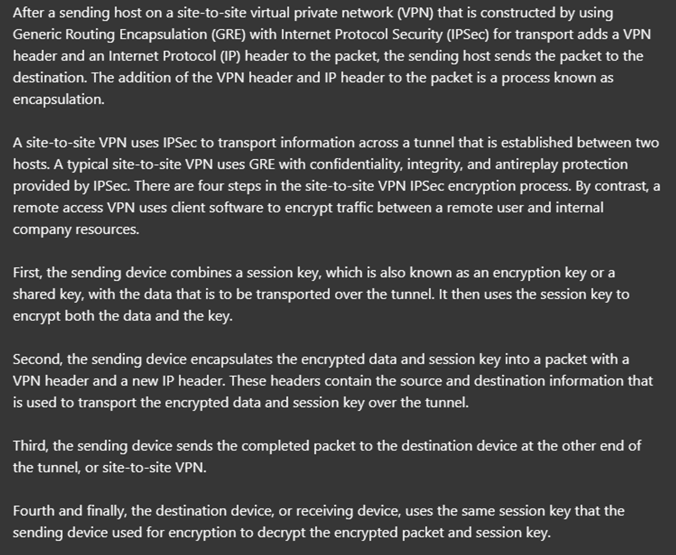
DMVPN
- DMVPN (Dynamic Multipoint VPN) is a Cisco-developed solution that enables routers to dynamically create a full mesh of IPSec tunnels without requiring manual configuration for each tunnel.
Configuration Steps:
-
Configure IPSec tunnels to a hub site.
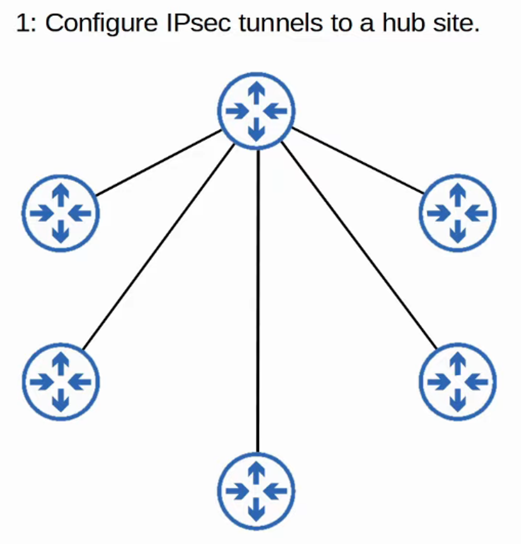
-
The hub router provides each router with information on how to form IPSec tunnels with other routers.
- DMVPN combines the configuration simplicity of hub-and-spoke (each spoke router needs only one tunnel configured) with the efficiency of direct spoke-to-spoke communication (spoke routers can communicate directly without traffic passing through the hub).
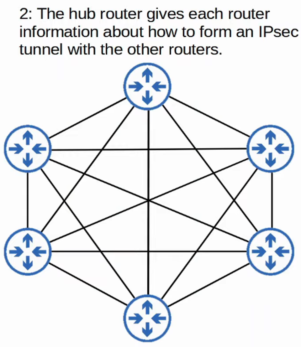
Remote-Access VPNs
-
While site-to-site VPNs create a point-to-point connection between two sites over the Internet, remote-access VPNs enable end devices (e.g., PCs, mobile phones) to securely access the company’s internal resources over the Internet.
-
Remote-access VPNs typically use TLS (Transport Layer Security), which also secures HTTPS (HTTP Secure). TLS was formerly known as SSL (Secure Socket Layer) and was developed by Netscape; it was renamed to TLS when standardized by the IETF.
-
VPN client software (e.g., Cisco AnyConnect) is installed on end devices (like company-provided laptops), allowing these devices to form secure tunnels to the company’s routers/firewalls acting as TLS servers. This setup enables end users to securely access resources on the company’s internal network without needing a direct connection.
Site-to-Site vs. Remote-Access VPNs
- Site-to-Site VPNs connect entire networks to each other, making them ideal for connecting branch offices, while Remote-Access VPNs allow individual users to connect to a network securely over the Internet, making them suitable for employees working remotely.
| Feature | Site-to-Site VPN | Remote-Access VPN |
|---|---|---|
| Connectivity | Connects two sites | Connects individual users to a network |
| Authentication | Typically uses IPSec | Often uses TLS (SSL) |
| Suitable For | Branch offices | Remote employees and mobile devices |
| Traffic Type | All traffic from one network to another | Individual user traffic to network resources |
Summary
This concludes the overview of WAN architectures, covering various connection types, technologies, and their applications in establishing reliable network connectivity across different geographic locations. Whether utilizing dedicated connections like leased lines or leveraging Internet-based VPNs, understanding these architectures is vital for designing and managing effective WAN solutions.
Tunnel Interface and OSPF Configuration Commands
Step 1: Create the Tunnel Interface
-
Enter Tunnel Interface Configuration Mode:
R1(config)# int tunnel <tunnel number>This command creates a new tunnel interface and enters the configuration mode for that interface.
-
Specify the Tunnel Source Interface:
tunnel source <interface>This command defines the physical interface (e.g.,
GigabitEthernet0/0) that will be used as the source for the tunnel. -
Set the Tunnel Destination IP Address:
tunnel destination <destination ip address>Here, you specify the IP address of the tunnel’s destination interface, which is the endpoint of the tunnel.
-
Assign an IP Address to the Tunnel Interface:
ip address <tunnel IP> <netmask>This command configures the IP address for the tunnel interface. Ensure the subnet is appropriate for your network design.
-
Configure a Default Route to the Service Provider Network:
R1(config)# ip route 0.0.0.0 0.0.0.0 <next hop interface>This command sets up a default route that directs traffic to the service provider network, enabling the tunnel interface to become administratively up.
Step 2: Configure OSPF on the Tunnel Routers
-
Enter OSPF Router Configuration Mode:
R1(config)# router ospf <ospf process ID>This command starts the configuration for OSPF (Open Shortest Path First) routing protocol.
-
Define the Network for the Tunnel Interface:
network <tunnel interface IP> <wildcard mask> area <area #>Since the tunnel interface represents a single host, use
0.0.0.0for the wildcard mask. This command tells OSPF to include the tunnel interface in the specified OSPF area. -
Define the Network for the Router Gateway:
network <router gateway IP> <wildcard mask> area <area #>Similarly, specify the router’s gateway IP address with a wildcard mask of
0.0.0.0to include it in the OSPF area. -
Set the Passive Interface:
passive-interface <router gateway IP interface>This command prevents the router from sending OSPF hello packets on the specified interface (router gateway), effectively making it a passive interface while still allowing it to receive OSPF updates.
Summary
By following these commands, you will successfully configure a tunnel interface on your router and set up OSPF neighbors for route sharing over the service provider network. Ensure that all IP addresses and interfaces are appropriately tailored to your specific network configuration.
If you have any specific configurations or scenarios you’d like to explore further, feel free to ask !