IP Phones and Voice VLANs
- Traditional telephony operates over the Public Switched Telephone Network (PSTN), often referred to as POTS (Plain Old Telephone System).
- Modern telephony uses IP phones, which employ VoIP (Voice over IP) technology, allowing phone calls over IP networks like the Internet.
- Many companies have switched from POTS to IP telephony for cost savings and advanced features. To avoid the need for extra cables and switch ports, IP phones include a built-in three-port switch, allowing both the phone and PC to share a single network connection.
Internal Structure of IP Phones
- IP phones have an internal 3-port switch:
- Port 1: Uplink to the external network switch.
- Port 2: Downlink to the PC.
- Port 3: Connection to the phone itself.
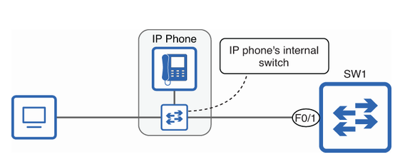 An IP phone’s internal switch allows both the phone and a PC to connect to a single port on SW1. One port of this mini-switch connects to the PC, one to SW1, and one to the IP phone’s internals.
Voice VLANs
- A PC and IP phone can share a switch port, but their traffic should be separated to prioritize voice calls. Using voice VLANs makes it easier to apply QoS policies and ensure smooth voice communication.
Segmenting voice and data traffic into separate subnets and VLANs
-
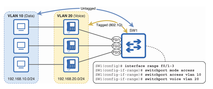
Access ports typically belong to a single VLAN, while trunk ports carry traffic from multiple VLANs using 802.1Q tagging. However, when an access port is configured with a voice VLAN, it handles traffic from two VLANs: the data VLAN (untagged) and the voice VLAN (tagged).
-
In this example, SW1’s ports are configured as access ports, with VLAN 10 assigned as the data VLAN (
switchport access vlan 10) and VLAN 20 as the voice VLAN (switchport voice vlan 20).
SW1(config)# interface range f0/1-3
SW1(config-if-range)# switchport mode access
SW1(config-if-range)# switchport access vlan 10
SW1(config-if-range)# switchport voice vlan 20- Next, I use the command
show interfaces f0/1 switchportto verify that F0/1 is recognized as an access port, even though it carries traffic for two VLANs: one for data and one for voice.
SW1(config-if-range)# do show interfaces f0/1 switchport
Name: Fa0/1
Switchport: Enabled
Administrative Mode: static access
Operational Mode: static access
Administrative Trunking Encapsulation: dot1q
Operational Trunking Encapsulation: native
Negotiation of Trunking: Off
Access Mode VLAN: 10 (VLAN0010)
Trunking Native Mode VLAN: 1 (default)
Administrative Native VLAN tagging: disabled
Voice VLAN: 20 (VLAN0020)
. . .
Power over Ethernet (PoE)
- IP phones often use Power over Ethernet (PoE), allowing them to get power through the same Ethernet cables used for data—no need for extra power cables. This reduces costs, cuts down on cable clutter, and allows phones to be placed where there are no nearby power outlets.
Tip
Power and data can share the same cable without interference because they use different frequency ranges.
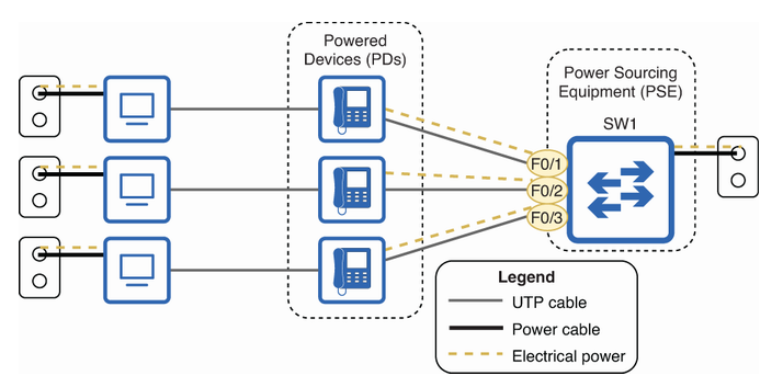 Power over Ethernet (PoE) works by having the switch (SW1) act as the Power Sourcing Equipment (PSE), supplying power to the IP phones, which are the Powered Devices (PDs). While SW1 and PCs get their power from wall outlets, the IP phones receive both power and data from SW1 through the same Ethernet cables. This eliminates the need for separate power cables for the phones.
Info
In addition to IP phones, a variety of devices can use PoE: IP cameras, wireless access points, access control devices like badge readers, door locks, and many others.
A Power Sourcing Equipment (PSE) must be careful when supplying power over an Ethernet cable to avoid damaging devices that can’t handle Power over Ethernet (PoE) or providing too much power to a Powered Device (PD). To do this, a PoE-enabled switch port follows these steps:
- Detection: When a device is connected, the PSE sends a low voltage to check if it can handle PoE.
- Classification: The PSE determines how much power the connected device needs and allocates the right amount.
- Startup: The PSE sends the correct voltage to power up the device.
- Normal operation: The PSE provides power to the device and monitors the current to ensure it remains safe and stable.
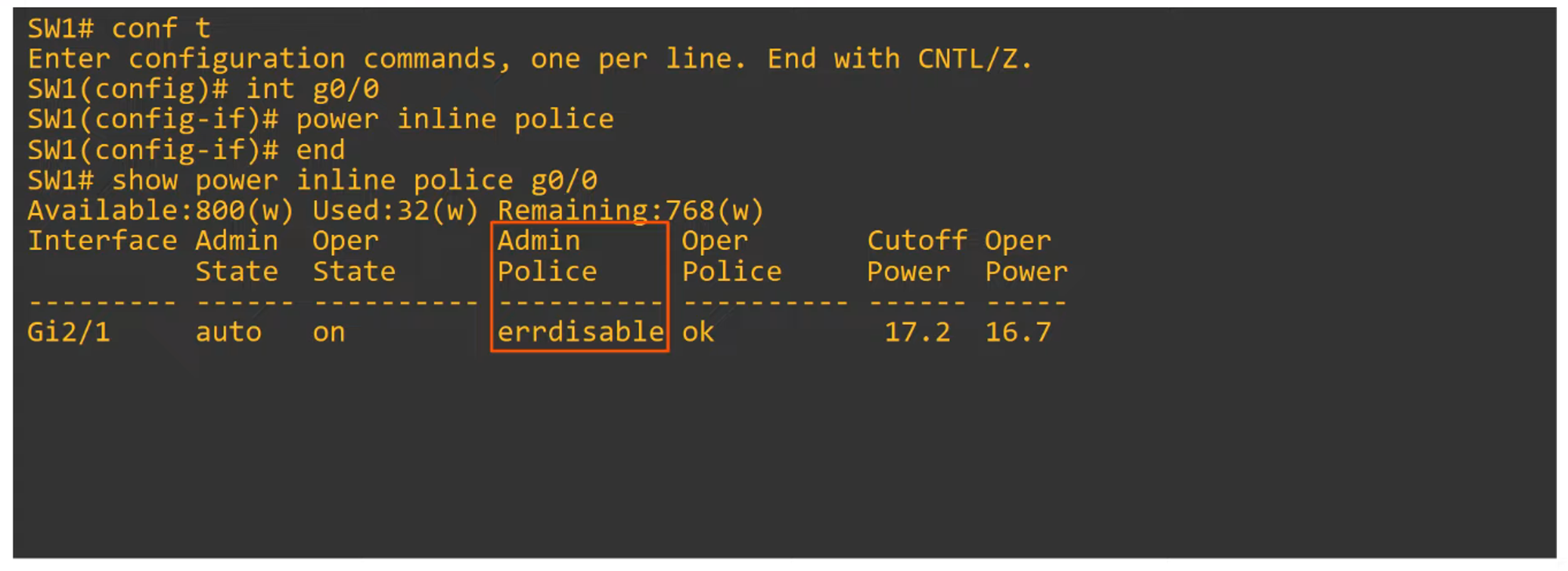
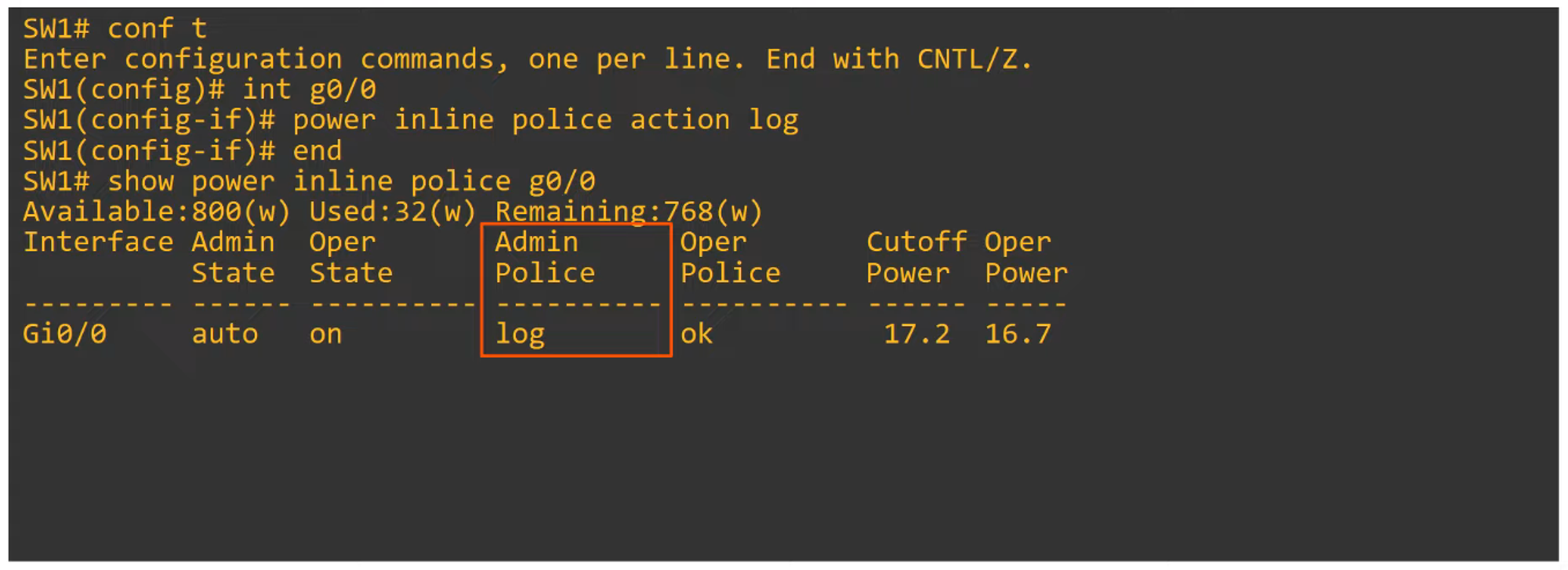
Power Policing
- Power policing helps control how much power a PD can draw:
- Command:
power inline police—this enforces default power policing. If a device draws too much power, the port will be disabled, and a syslog message is generated. - Command:
power inline police action err-disable—puts the interface in an error-disabled state if the PD exceeds its power allowance. The interface must be manually restarted withshutdownandno shutdowncommands.
- Command:
- If you want the port to remain active even if power exceeds the limit, use the command
power inline police action log. This logs the incident without disabling the interface but it will restart it and that will cause de PD(power device) to restart.
Introduction to Quality of Service (QoS)
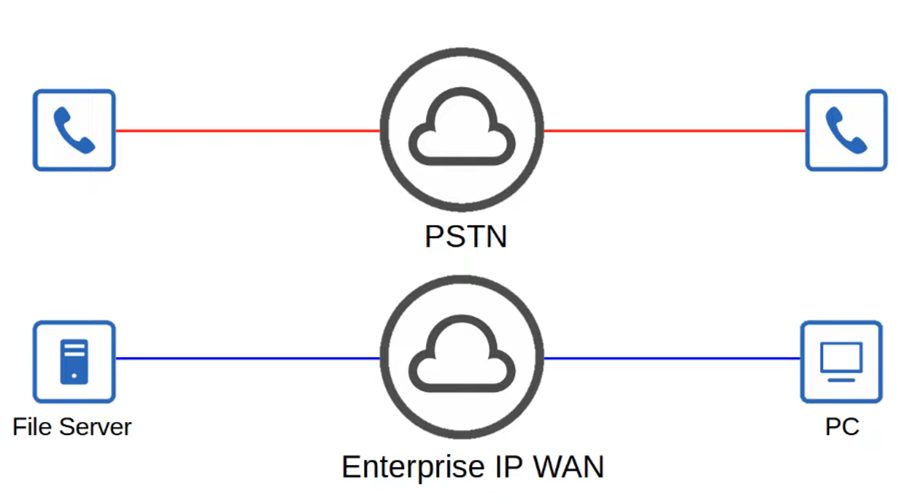
- In earlier times, voice traffic (PSTN) and data traffic (IP networks) were on separate networks. QoS was unnecessary because there was no competition for bandwidth.
- In modern converged networks, both voice and data share the same IP infrastructure. While this saves costs and supports advanced features (e.g., Cisco WebEx, MS Teams), it creates competition for bandwidth, leading to potential performance issues.
- Quality of Service (QoS) is a set of tools that prioritize certain types of network traffic to ensure the best possible performance, particularly for voice and video.
Key QoS Metrics
QoS aims to manage the following network traffic characteristics:
- Bandwidth:
- Refers to the capacity of the link (measured in bits per second).
- QoS can reserve portions of a link’s bandwidth for critical traffic types.
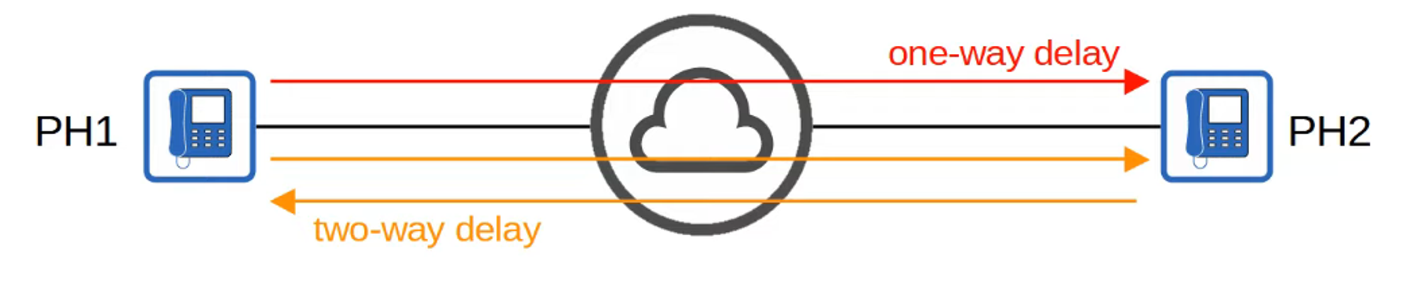
- Delay:
- One-way delay: Time for traffic to travel from source to destination.
- Round-trip delay: Time for traffic to travel to the destination and back.
- Jitter:
- The variation in delay between packets sent by the same application. IP phones mitigate jitter with jitter buffers, providing consistent audio delays.
- Packet Loss:
- The percentage of packets that fail to reach their destination. Loss can be caused by network congestion or faulty cables, and devices may discard packets when their packet queues are full.
Recommended Standards for Voice Traffic
To ensure good interactive audio quality, the following thresholds should be met:
- One-way delay: 150 milliseconds or less.
- Jitter: 30 milliseconds or less.
- Packet loss: 1% or less.
Failure to meet these standards can result in poor call quality, with noticeable delays, echoes, or choppy audio.
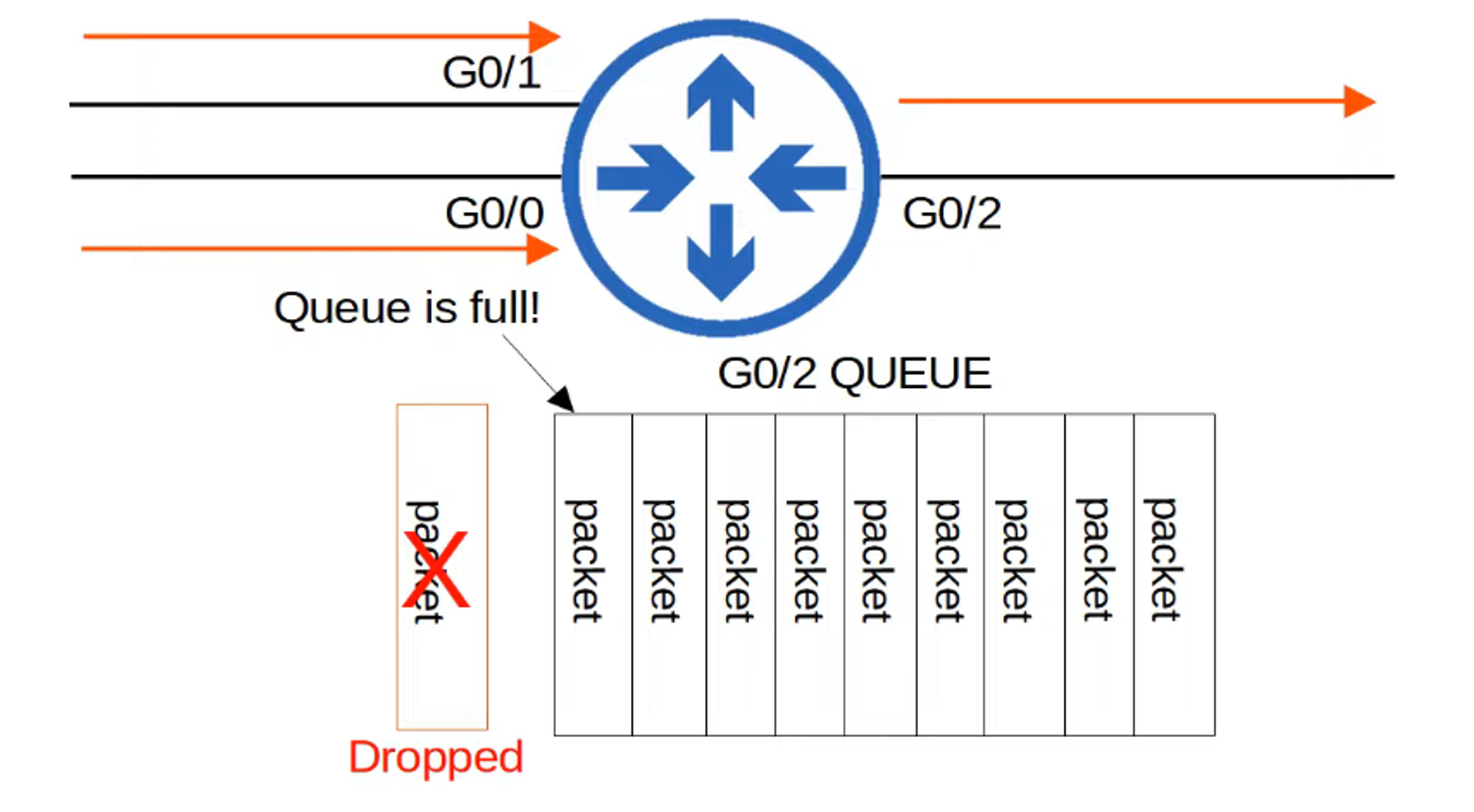
QoS Queuing and Tail Drop
- Network devices often receive traffic faster than they can transmit. Incoming traffic is stored in a queue, where it waits its turn to be forwarded.
- By default, queues follow a First-In, First-Out (FIFO) policy, meaning packets are transmitted in the order they arrive.
- If the queue fills up, any additional packets are dropped—a condition known as tail drop.
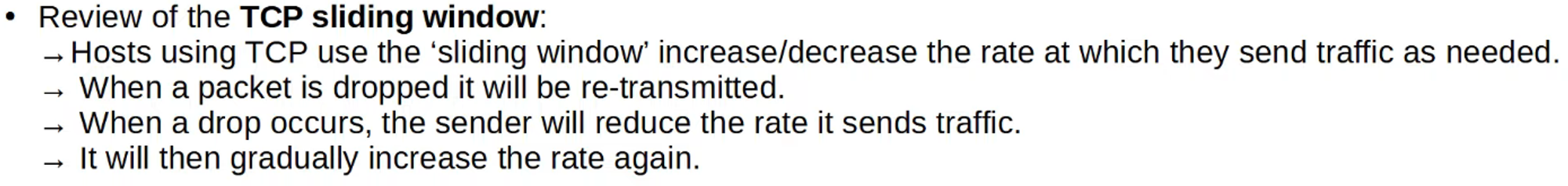
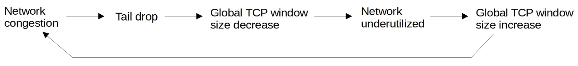
TCP Global Synchronization
- Tail drop can lead to TCP global synchronization, where multiple TCP hosts simultaneously slow down their transmission rates due to packet loss and then ramp up again, causing network congestion in waves.
Random Early Detection (RED)
- RED helps avoid tail drop by randomly dropping packets before the queue is full, encouraging TCP flows to reduce their transmission rates before congestion becomes severe.
- Weighted Random Early Detection (WRED) takes this concept further by applying different thresholds to different types of traffic, ensuring critical traffic (e.g., voice or video) is less likely to be dropped.
Further details on traffic classes and how QoS works will be covered in Day 47.