WHAT IS ETHERCHANNEL?
EtherChannel is a technology that enables you to group multiple physical interfaces into a single logical interface, allowing them to function as if they were a single interface.
- Layer 2 EtherChannel: This involves a group of switch ports operating as one interface.
- Layer 3 EtherChannel: This includes a group of routed ports that work as a single interface, to which you can assign an IP address.
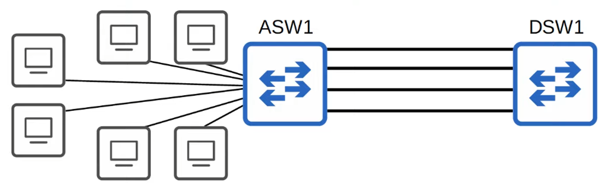
Oversubscription occurs when the bandwidth of interfaces connected to end hosts exceeds the bandwidth of the connection to distribution switches. Some level of oversubscription is generally acceptable, but excessive oversubscription can lead to congestion.
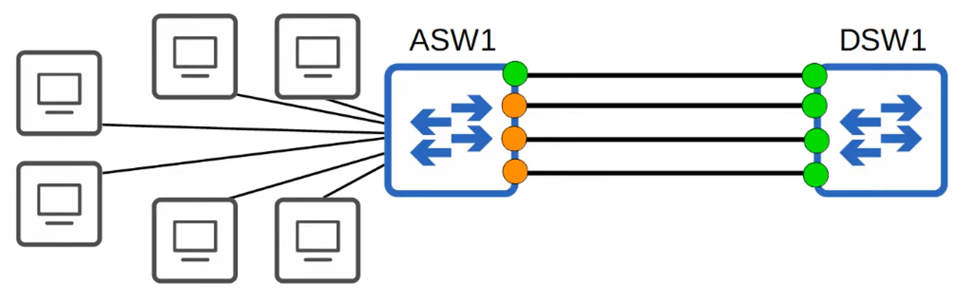
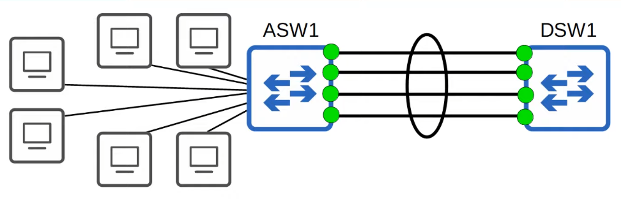
If you connect two switches with multiple links, the Spanning Tree Protocol (STP) will disable all except one link (as indicated by green and orange lights on ASW1).
Why?
- If all of ASW1’s interfaces were forwarding, Layer 2 loops could form between ASW1 and DSW1, potentially causing a broadcast storm—a highly undesirable situation.
- The inactive links remain unused until the active link fails, at which point one of the inactive links will take over.
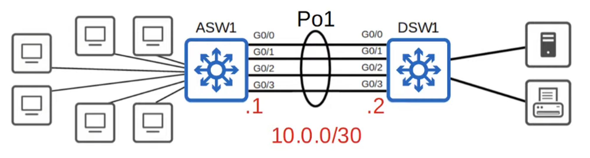
In network topology diagrams, EtherChannel is often represented with a circle around multiple connections, indicating the grouped interfaces.
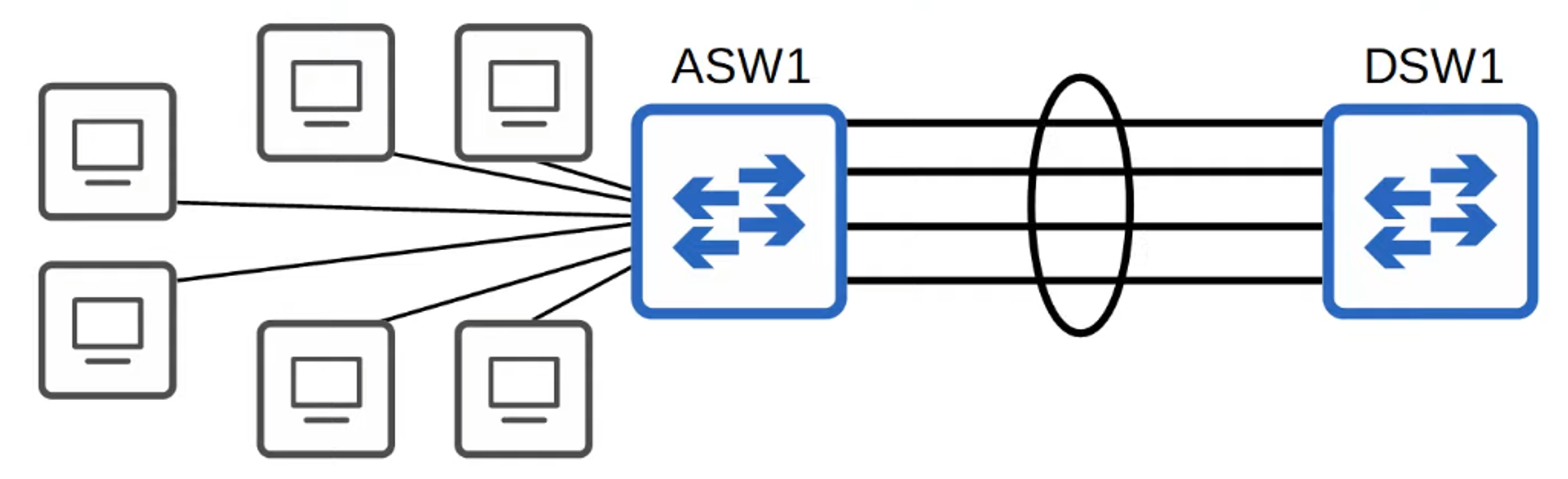
- EtherChannel groups multiple channels to act as a single interface.
- STP treats this group as a single interface.
Traffic using EtherChannel is load-balanced across the physical interfaces within the group. An algorithm determines which traffic uses which physical interface, ensuring efficient data distribution.
Alternative Names for EtherChannel:
- Port Channel
- LAG (Link Aggregation Group)
HOW DOES ETHERCHANNEL LOAD-BALANCE?
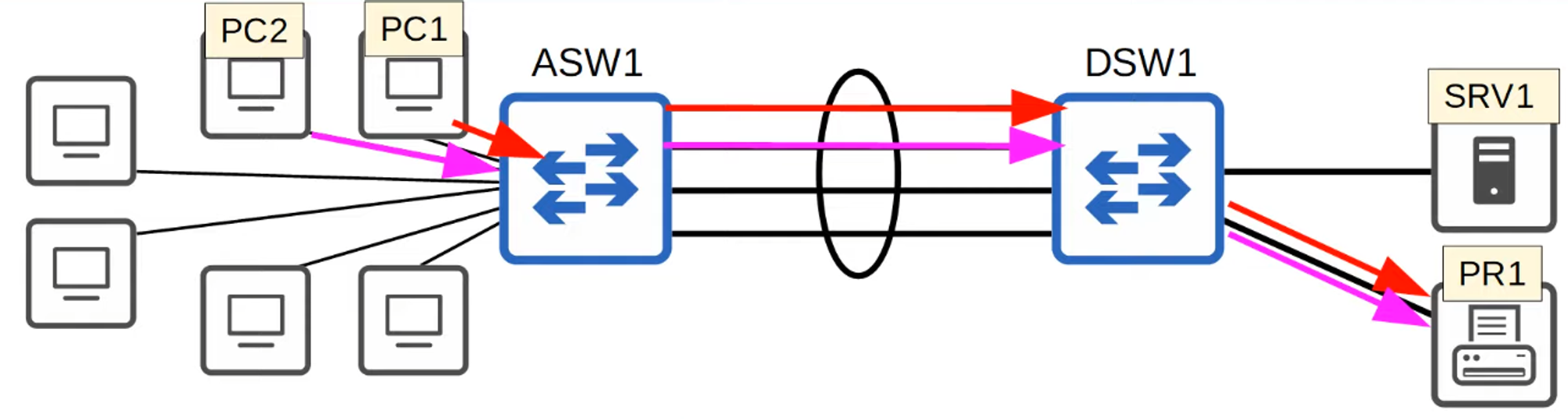
- EtherChannel load-balances traffic based on “flows,” which represent communication between two nodes in the network.
- Frames within the same flow are forwarded using the same physical interface. This prevents frames from arriving out of order, which could otherwise cause issues.
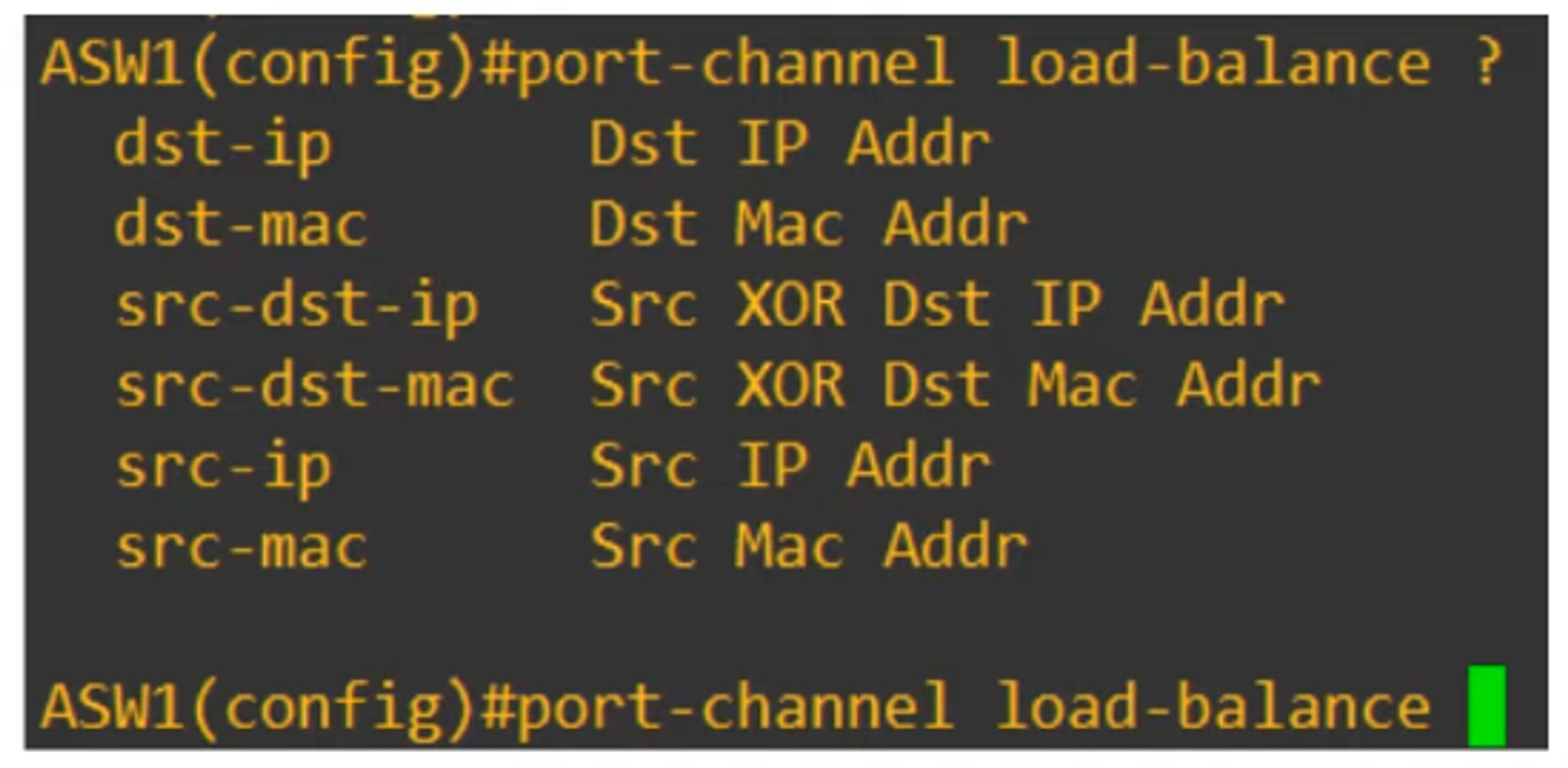
- You can modify the inputs used in the interface selection calculation for flows. These inputs include:
- Source MAC Address
- Destination MAC Address
- Source and Destination MAC Address
- Source IP Address
- Destination IP Address
- Source and Destination IP Address
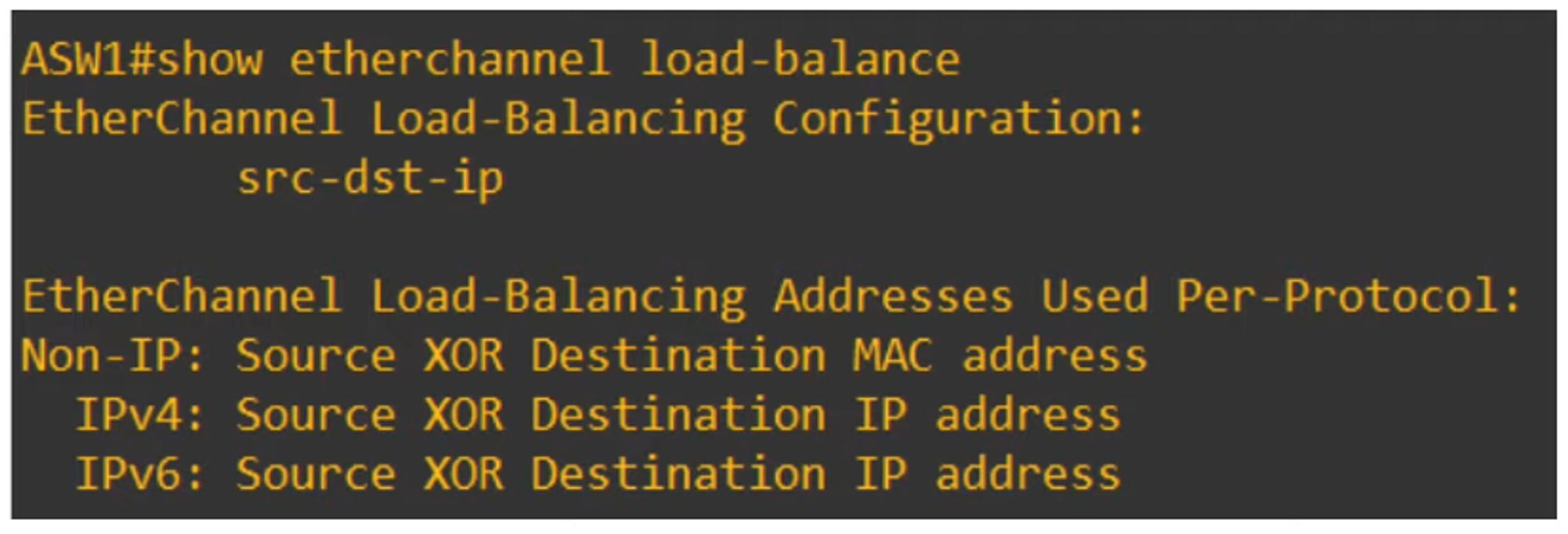
To view the load-balancing configuration:
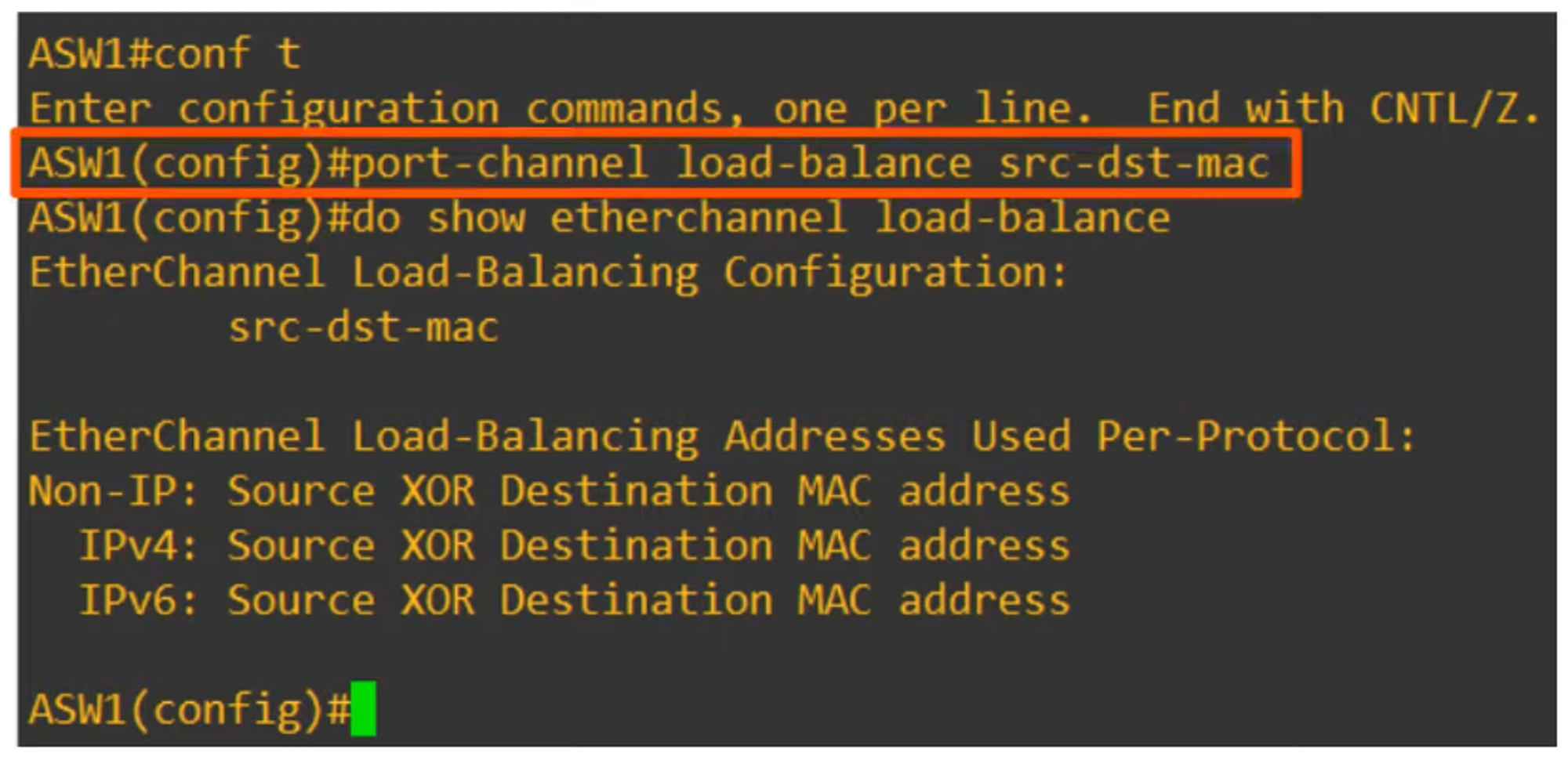
To change the load-balancing method:
HOW TO CONFIGURE LAYER 2 / LAYER 3 ETHERCHANNELS
There are three methods for configuring EtherChannel on Cisco switches:
-
PAgP (Port Aggregation Protocol)
- A Cisco proprietary protocol.
- Dynamically negotiates the creation and maintenance of EtherChannel, similar to how DTP (Dynamic Trunking Protocol) works for trunks.
-
LACP (Link Aggregation Control Protocol)
- An industry-standard protocol (IEEE 802.3ad).
- Also dynamically negotiates the creation and maintenance of EtherChannel.
-
Static EtherChannel
- Does not use a protocol to determine whether an EtherChannel should be formed.
- Interfaces are statically configured to form an EtherChannel.
Up to 8 interfaces can be grouped into a single EtherChannel (LACP supports up to 16, but only 8 will be active, with the others in standby mode).
PAgP CONFIGURATION
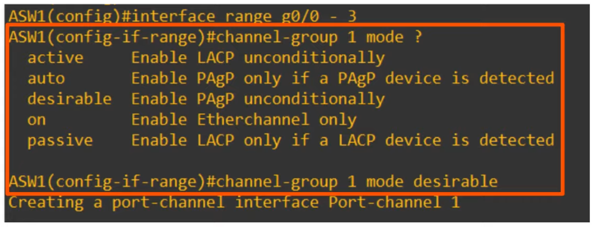
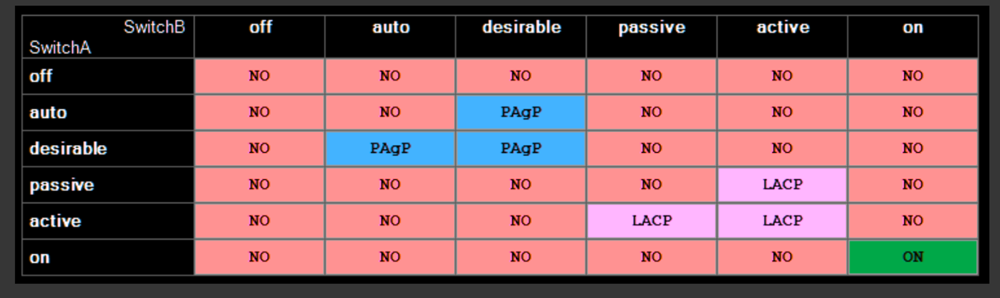
💡 Note that “auto” and “desirable” are the only modes available for PAgP.
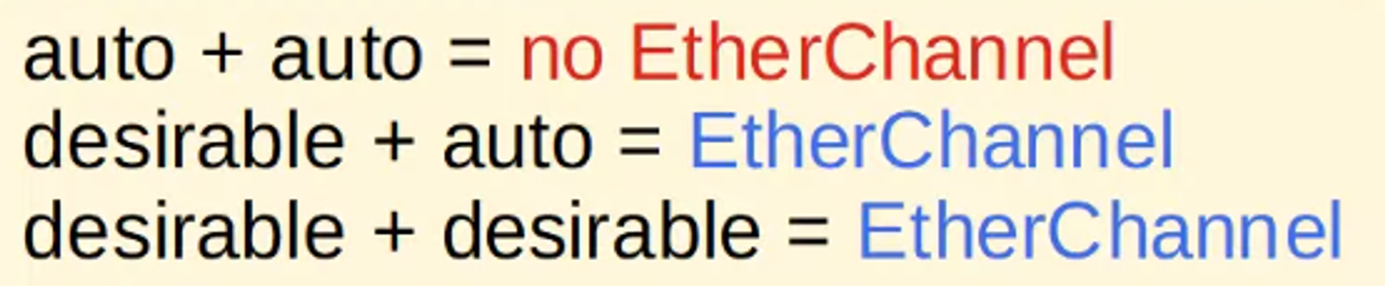
In PAgP, EtherChannel is formed when the interfaces are in “desirable” or “auto” mode.
💡 Example: AWS1(config-if-range)# channel-group 1 mode desirable
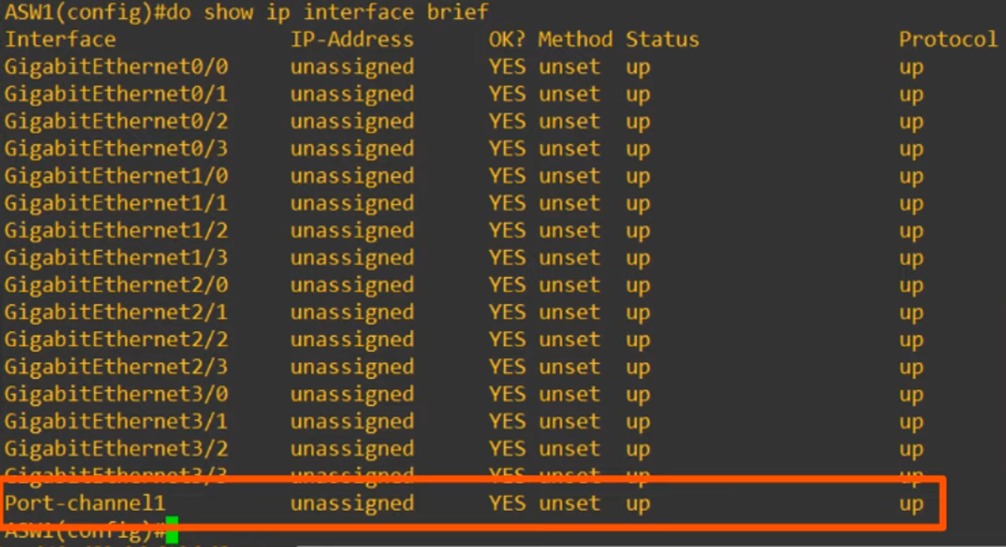
This command creates a port-channel interface, Port-channel1.
- The “channel-group” number must match for member interfaces on the same switch.
- However, it does not need to match the “channel-group” number on the other switch (e.g., channel-group 1 on ASW1 can form an EtherChannel with channel-group 2 on DSW1).
LACP CONFIGURATION
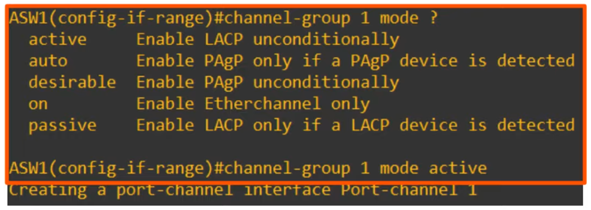
💡 Note that “active” and “passive” are the only modes available for LACP.
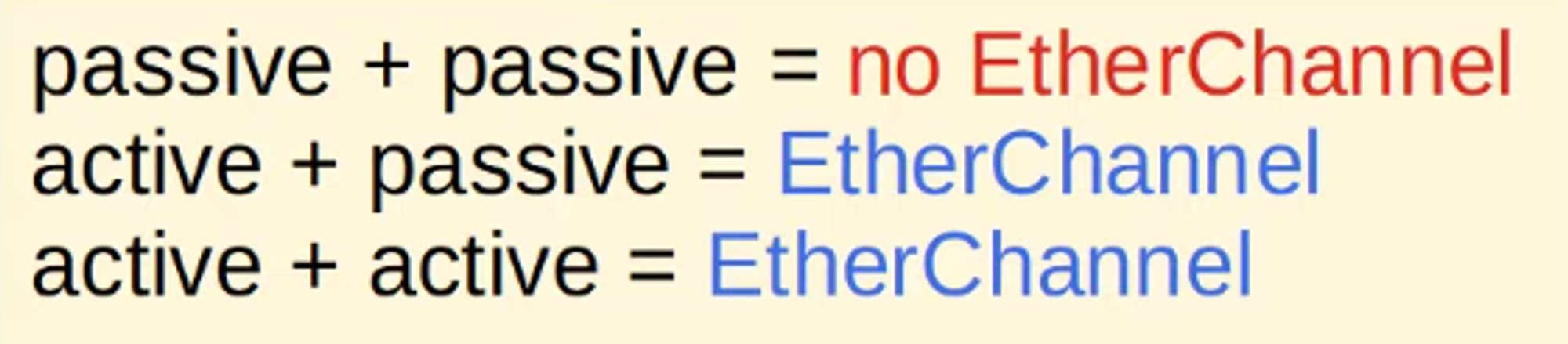
LACP forms an EtherChannel when interfaces are in “active” or “passive” mode.
- The “channel-group” number must match for member interfaces on the same switch.
- It doesn’t need to match the “channel-group” number on the other switch.
STATIC ETHERCHANNEL CONFIGURATION
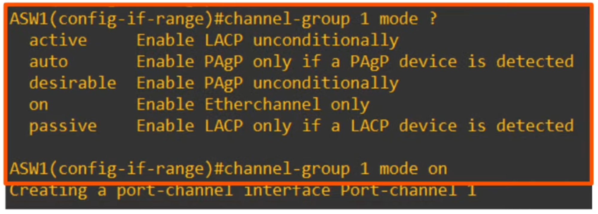
💡 Note that “on” is the only mode available for static EtherChannel.
- On mode works only with On mode on the other side.
- On + desirable = Does not work
- On + active = Does not work
MANUALLY CONFIGURING THE NEGOTIATION PROTOCOL
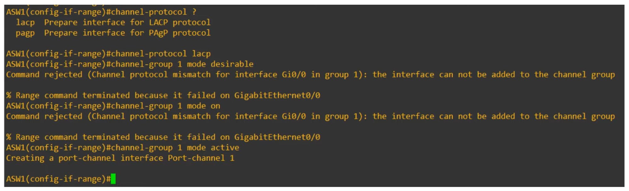
You have two options for configuring the negotiation protocol:
- LACP Protocol
- PAgP Protocol
(Above shows a protocol mismatch error because LACP does not support “desirable” mode, which is only supported by PAgP.)
For instance, channel-group 1 mode active works because LACP supports “active.”
AFTER CONFIGURING THE ETHERCHANNEL MODE
Next, configure the port interface:
The show running-config command shows interface Port-channel1 in the configuration.
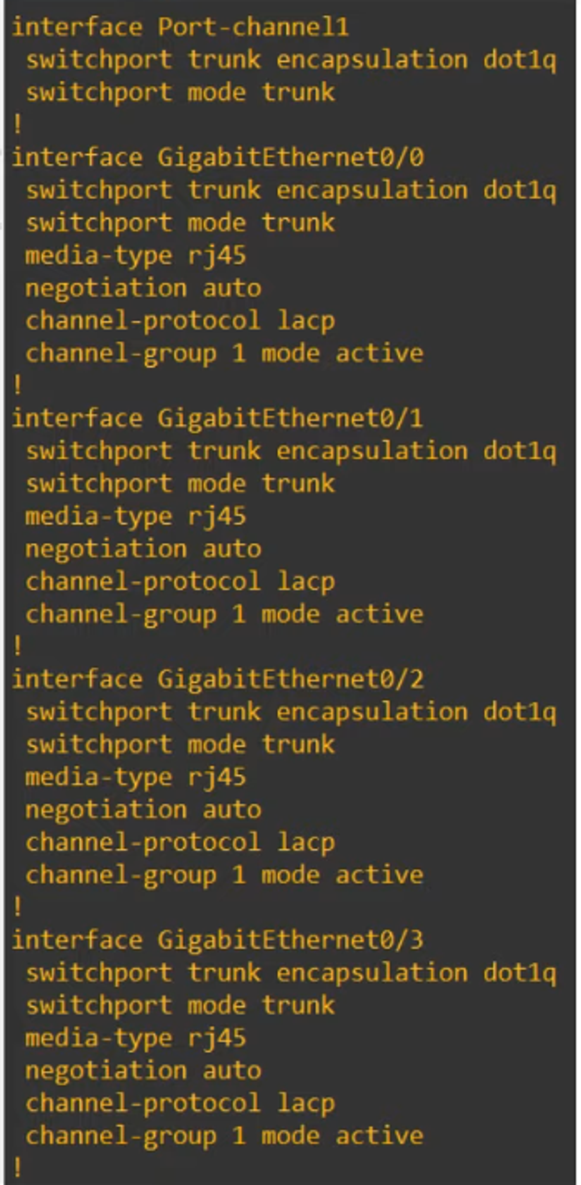
💡 Note that the physical interfaces (g0/0-g0/3) were auto-configured by the Port-channel1 configuration.
IMPORTANT NOTES ABOUT ETHERCHANNEL CONFIGURATION
-
Member interfaces must have matching configurations:
- Same duplex (Full/Half)
- Same speed
- Same switchport mode (Access/Trunk)
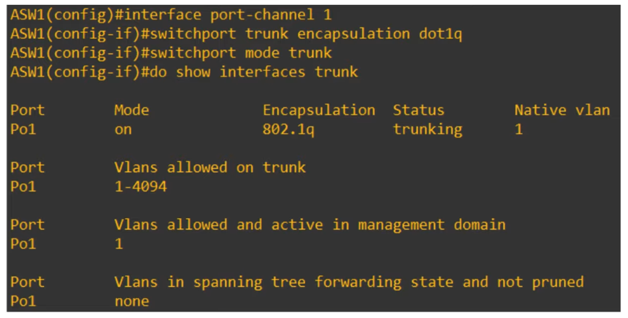
- Same allowed VLANs/Native VLAN (for trunk interfaces)
-
If an interface’s configuration does not match the others, it will be excluded from the EtherChannel.
VERIFYING ETHERCHANNEL STATUS
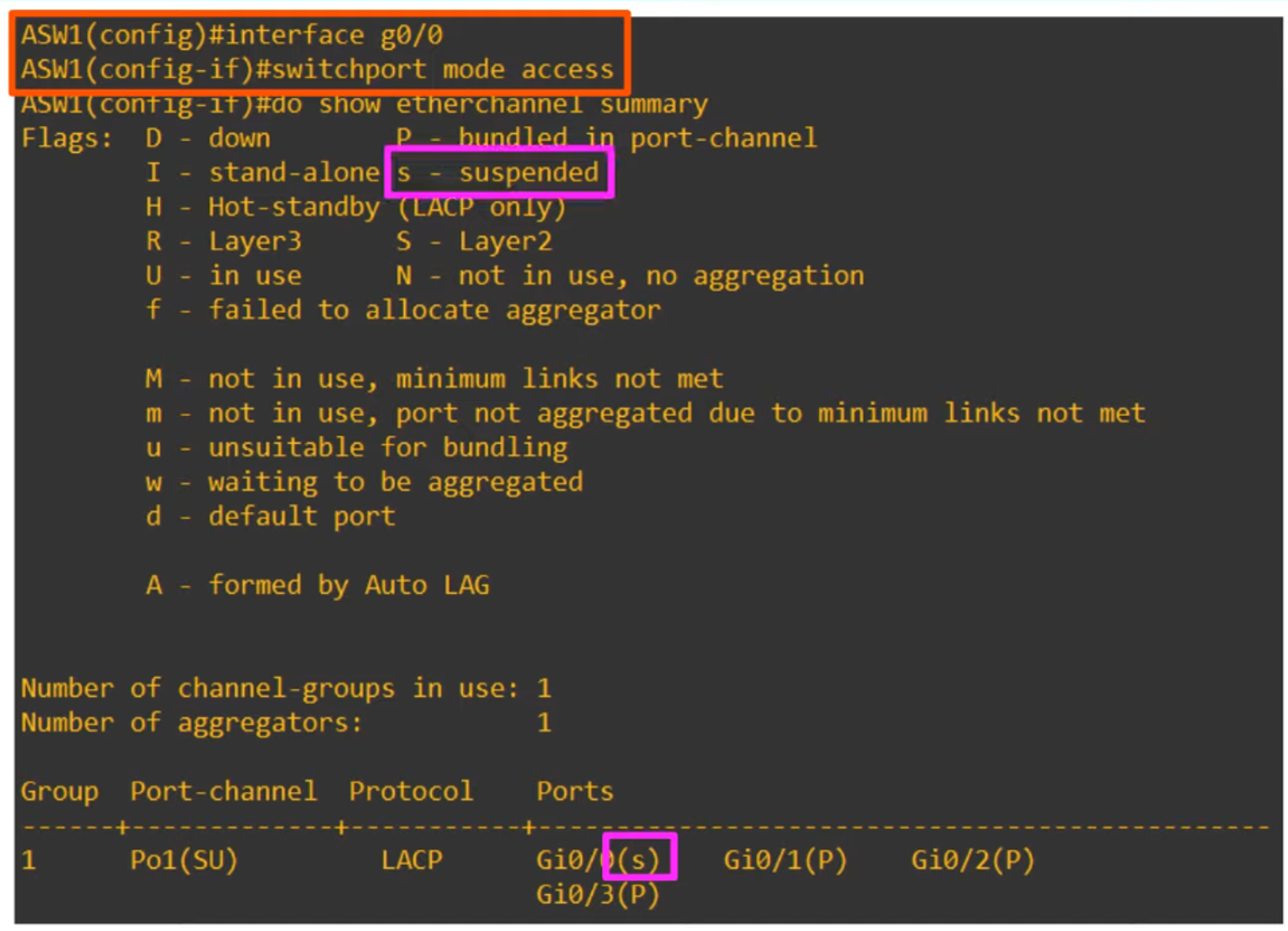
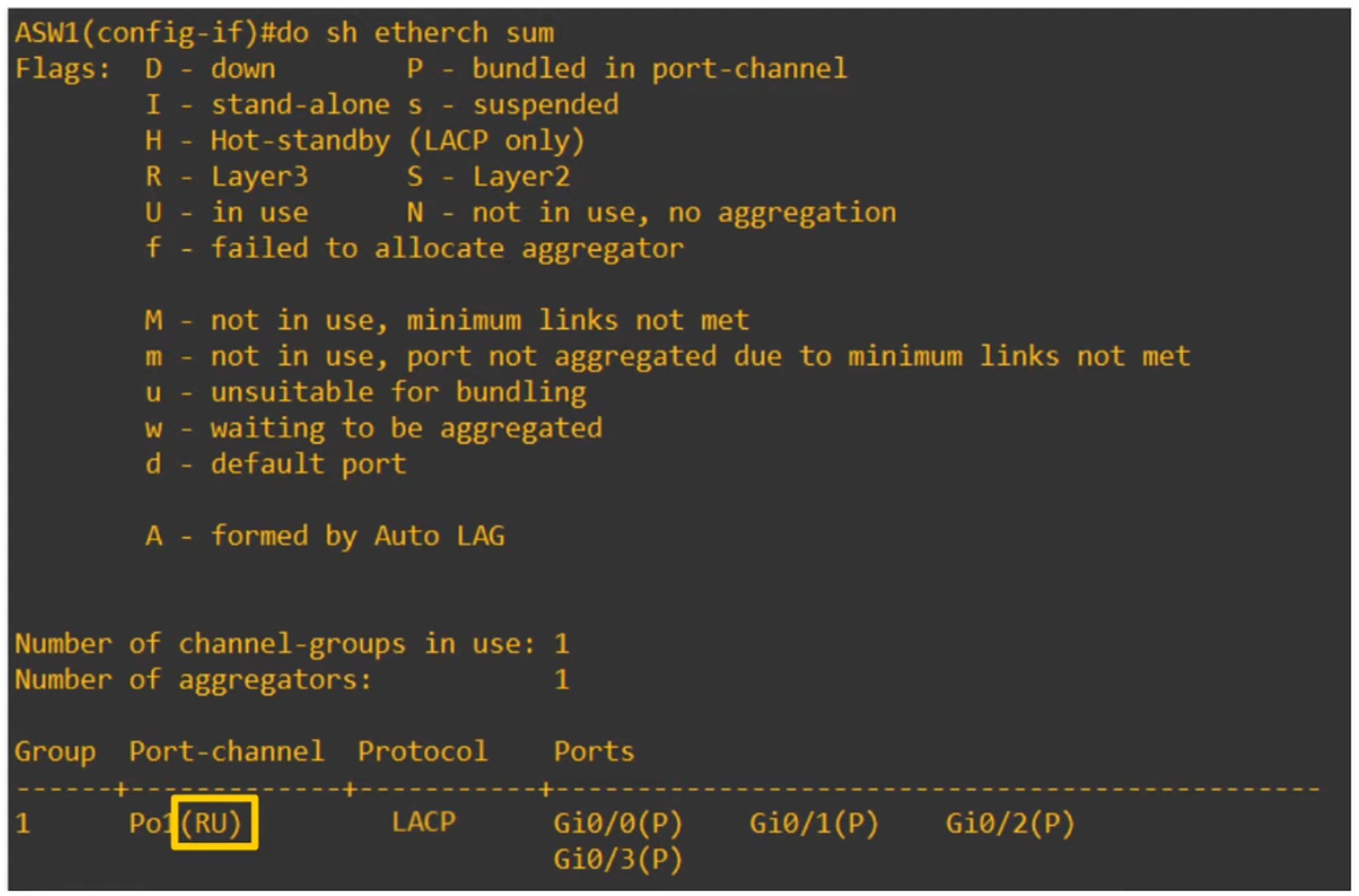
💡 Use show etherchannel summary to verify the EtherChannel status.
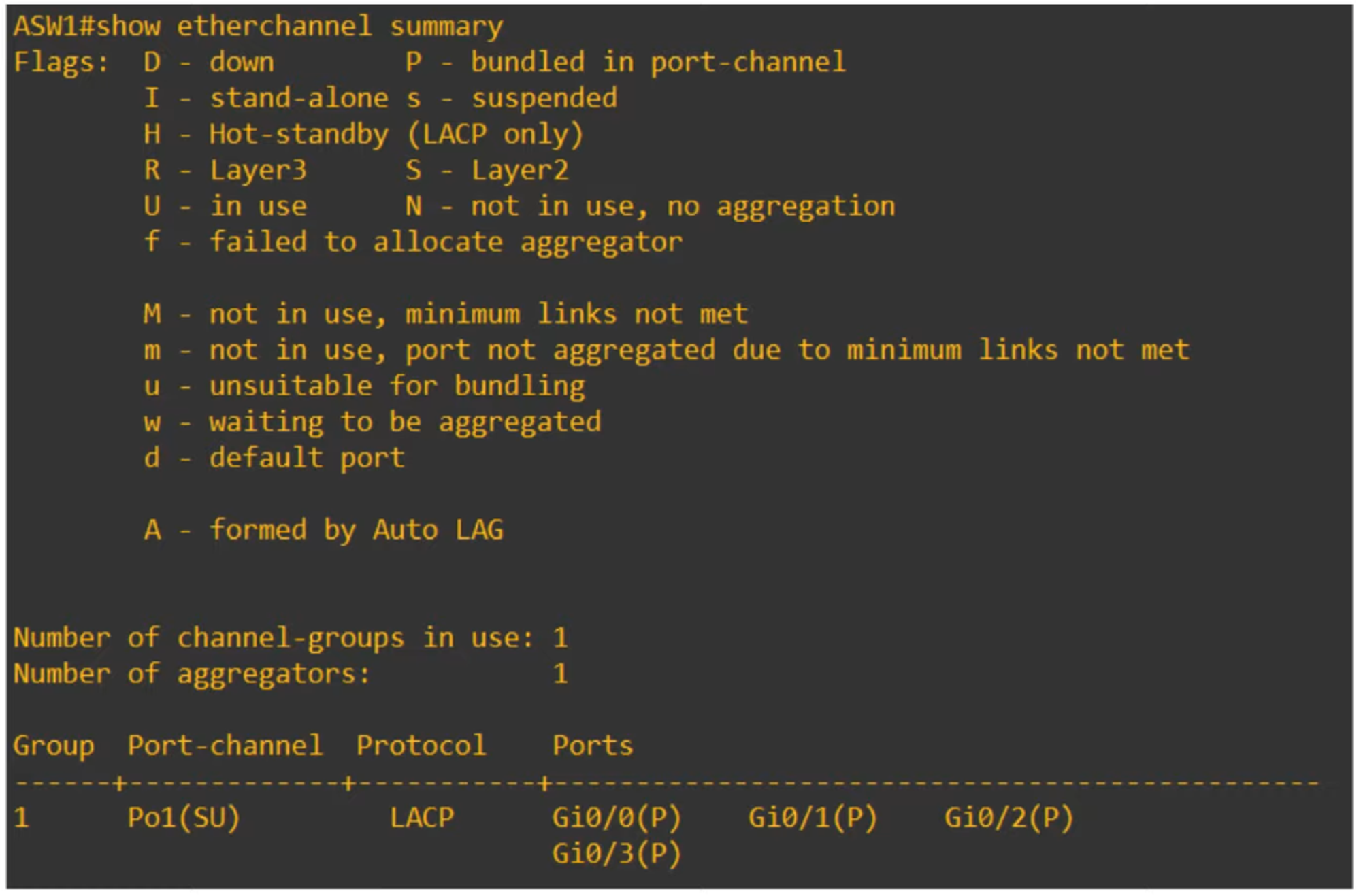
The summary shows information such as the protocol used by the EtherChannel (e.g., LACP) and the interfaces involved in the EtherChannel (P = bundled in port-channel).
Other Flags:
- D = Down
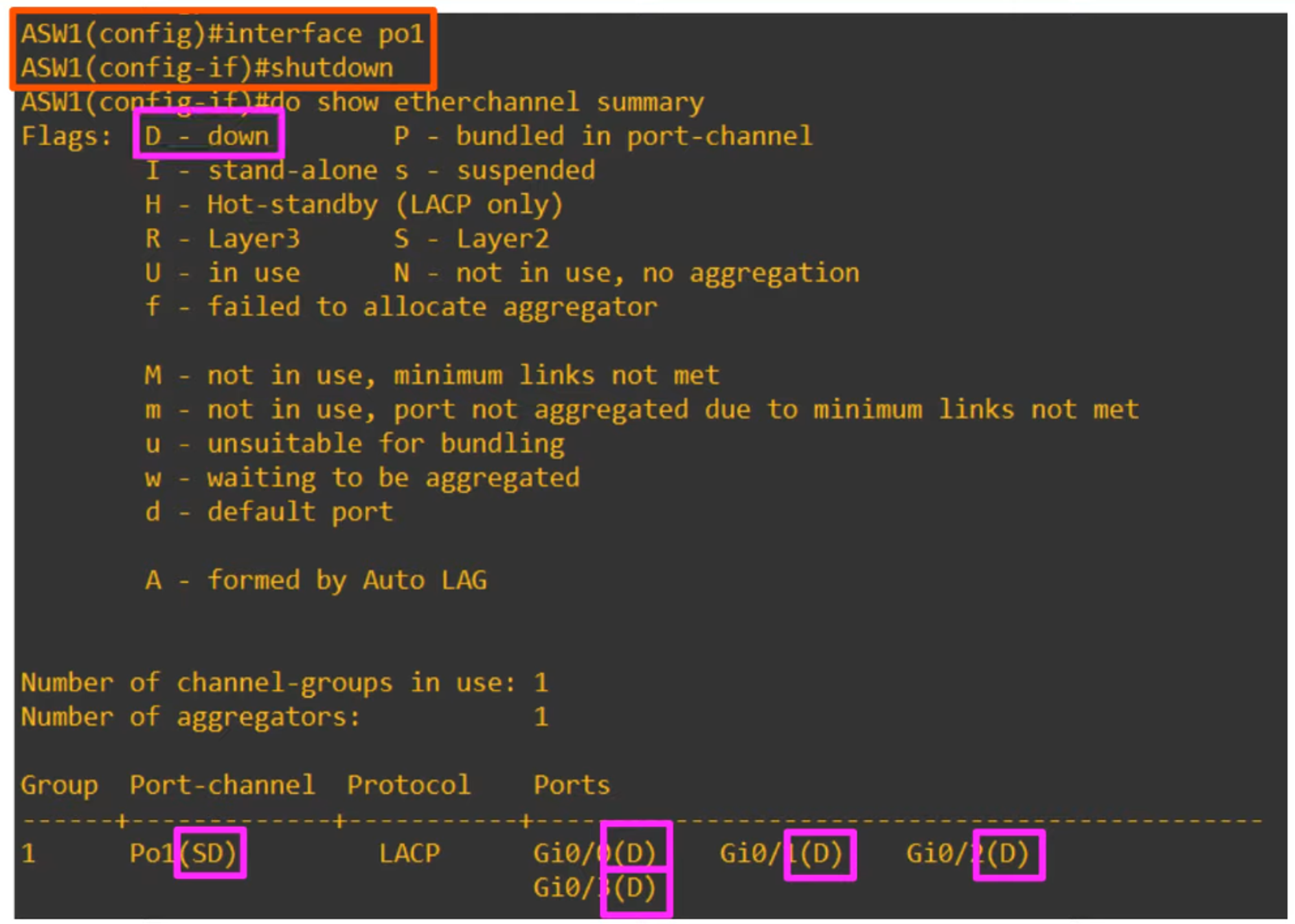
If a member interface’s configuration is inconsistent with the others, it will be suspended (s = suspended).
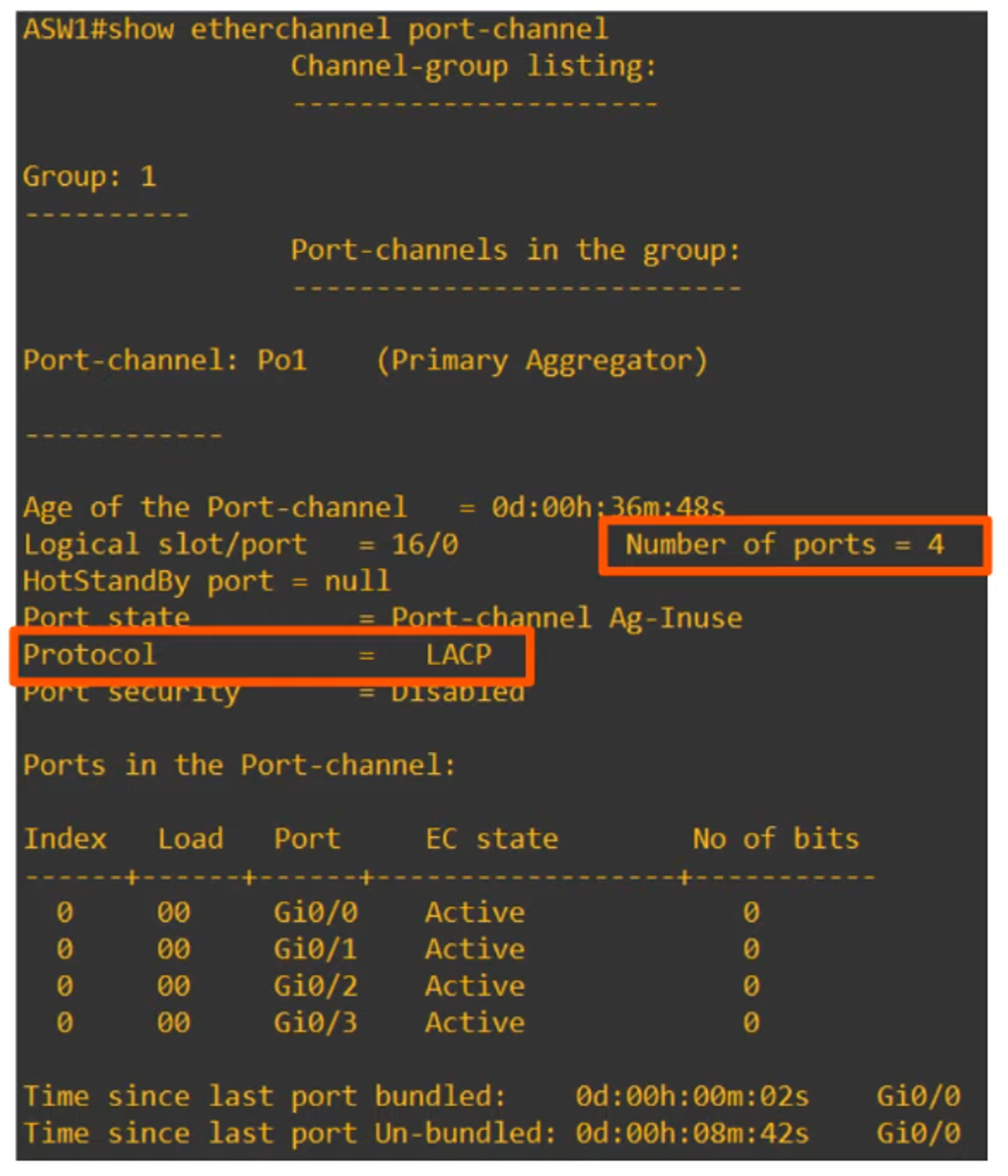
Another useful command:
- 💡
show etherchannel port-channeldisplays information about the virtual port-channel interfaces on a switch.
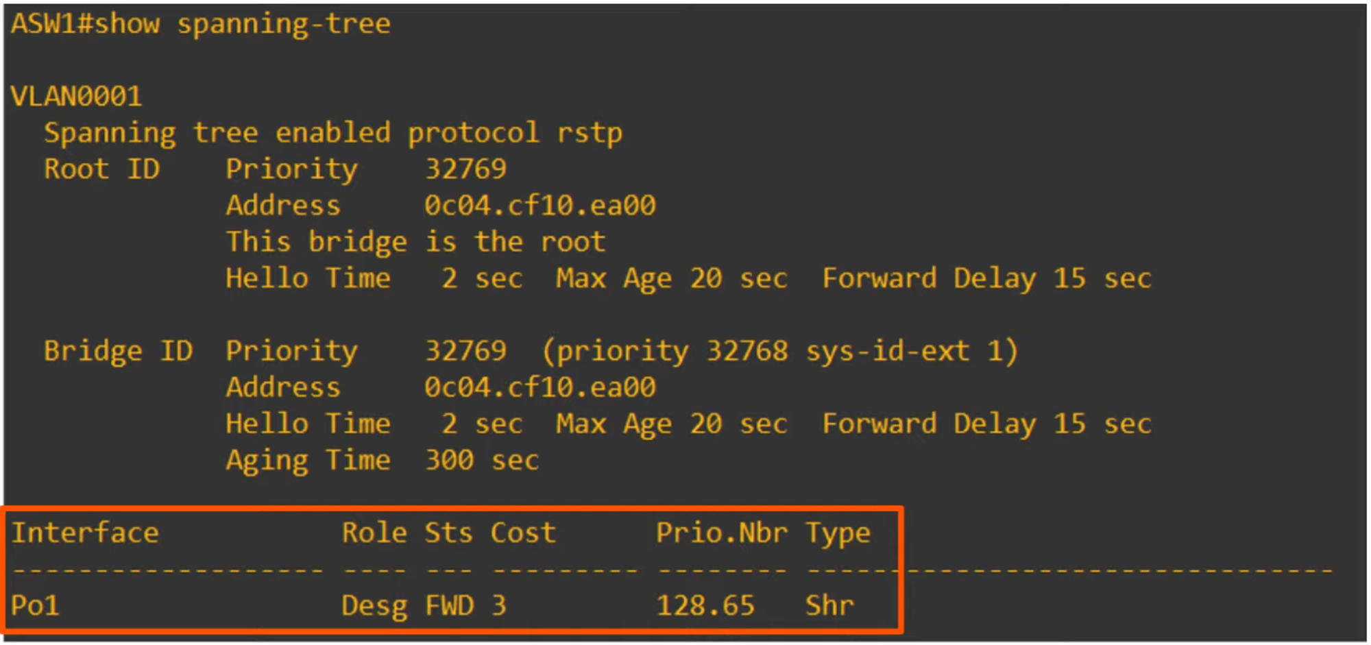
💡 The show spanning-tree command will show the single EtherChannel port interface.
LAYER 3 ETHERCHANNELS
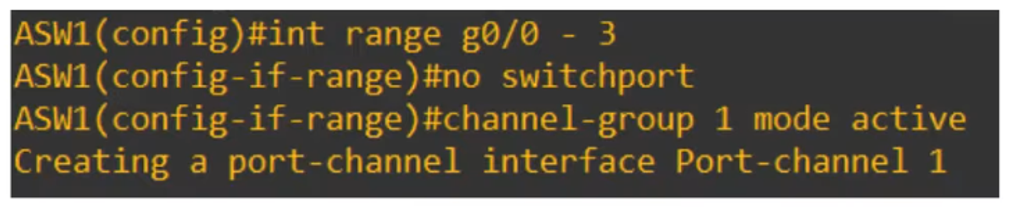
How to Configure a Layer 3 EtherChannel (from a clean configuration):
💡 show running-config verifies the configuration.
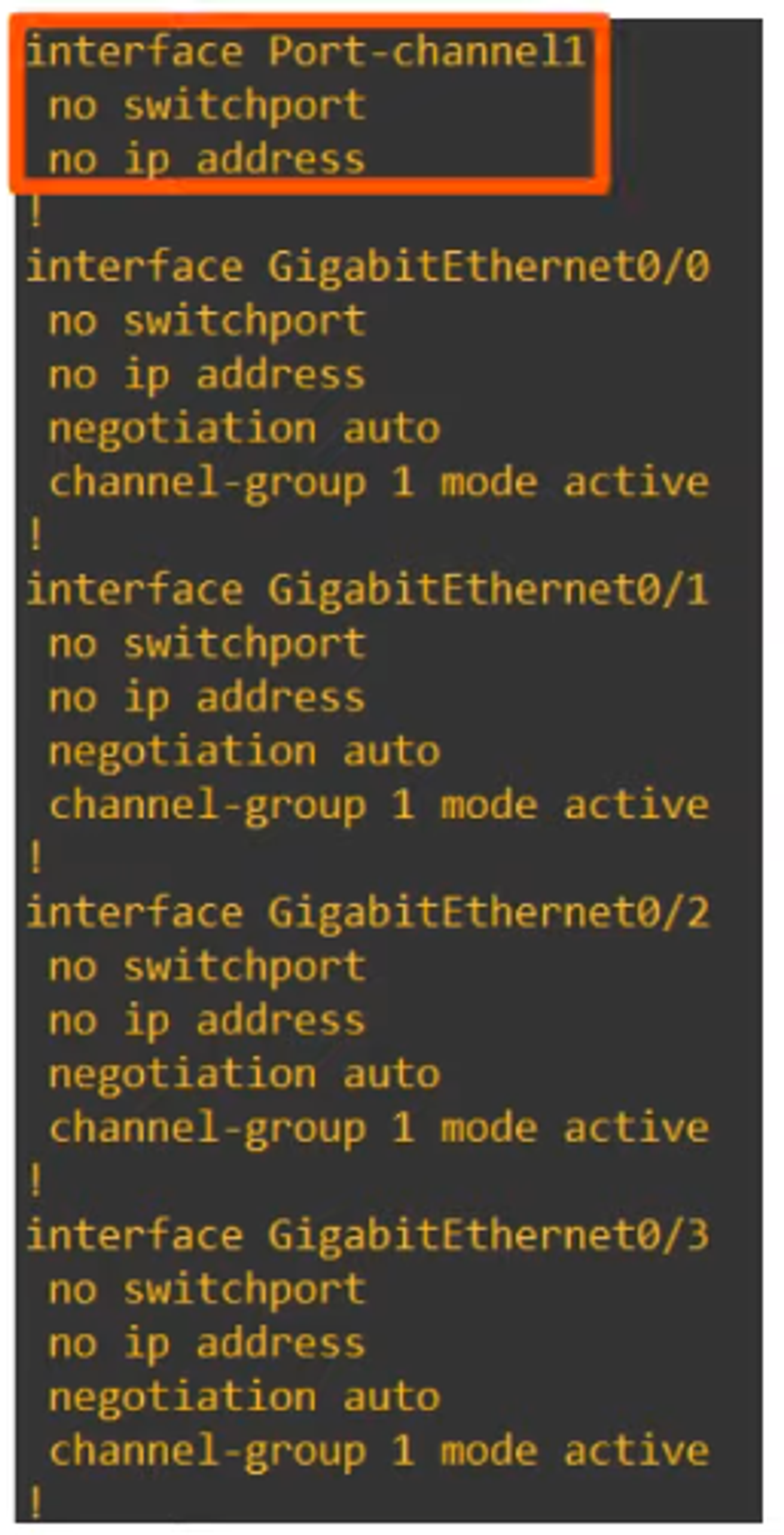
Note: There is no switchport or IP interface configured here.
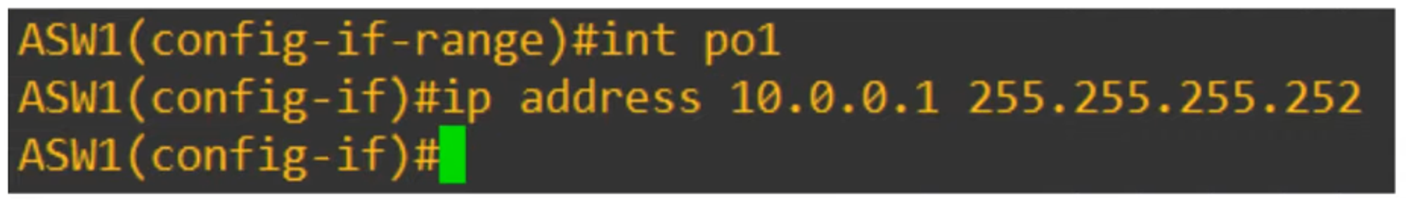
To configure the IP address, you must do it directly on the port interface.
The status RU in the configuration indicates:
- R = Layer 3
- U = In use
COMMANDS LEARNED IN THIS CHAPTER
SW(config) port-channel load-balance *mode*- Configures the EtherChannel load-balancing method on a switch.
SW# show etherchannel load-balance- Displays information about the load-balancing settings.
SW(config-if)# channel-group *number* mode {desirable | auto | active | passive | on}- Configures an interface to be part of an EtherChannel.
SW# show etherchannel summary- Displays a summary of EtherChannels on a switch.
SW# show etherchannel port-channel- Displays information about the virtual port-channel interfaces on a switch.