Comparison of STP Versions (Standard vs. Cisco)
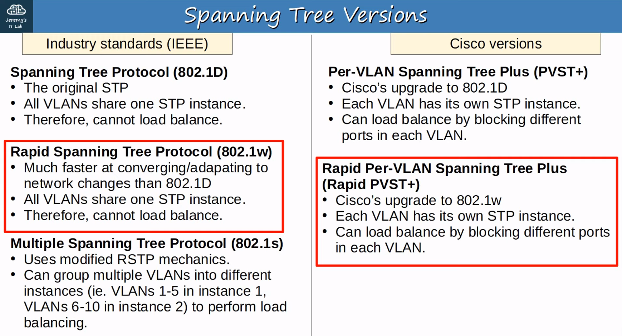
In most use cases, the focus is on 802.1w (Rapid Spanning Tree Protocol, or RSTP). For extremely large networks, MSTP (802.1s) might be more appropriate.
What is Rapid Per-VLAN Spanning Tree Plus (Rapid PVST+)?
Unlike the traditional 802.1D STP, RSTP is not a time-based spanning tree algorithm. RSTP significantly improves on the 30 seconds or more required by 802.1D to transition a link to a forwarding state. The core of RSTP is a new bridge-to-bridge handshake mechanism that allows ports to transition directly to the forwarding state.
Similarities Between STP and RSTP
- Purpose: Both RSTP and STP block specific ports to prevent Layer 2 loops.
- Root Bridge Election: RSTP elects a root bridge using the same criteria as STP.
- Root Ports: RSTP and STP use the same rules for selecting root ports.
- Designated Ports: Both protocols use the same criteria for selecting designated ports.
Differences Between STP and RSTP
Port Costs
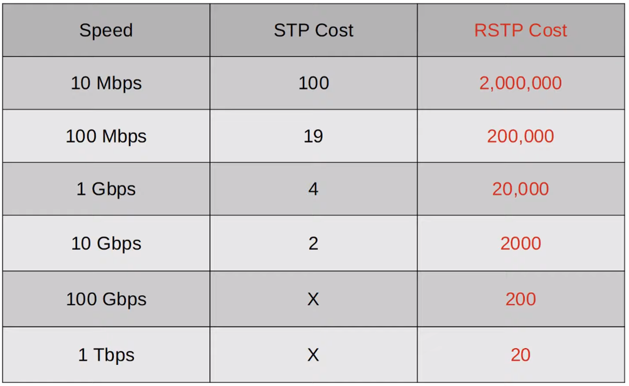
(Familiarize yourself with the port costs for STP and RSTP.)
RSTP Port States
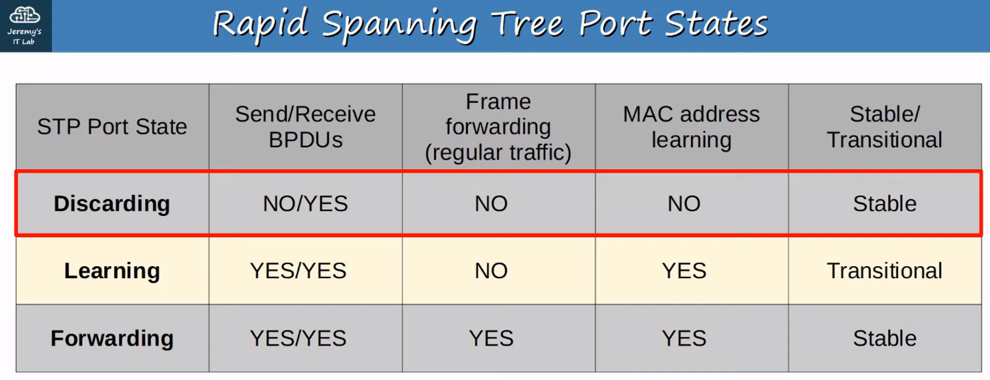
- Admin Disabled Port: A port administratively disabled (using the “shutdown” command) is in the Discarding state.
- Blocking Port: A port enabled but blocking traffic to prevent Layer 2 loops is also in the Discarding state.
RSTP Roles
- Root Port: Remains unchanged in RSTP. It is the port closest to the root bridge, and the root bridge itself does not have a root port.
- Designated Port: Remains unchanged in RSTP. It is the port on a segment (collision domain) that sends the best BPDU, with only one per segment.
- Non-Designated Port: Split into two roles in RSTP:
- Alternate Port
- Backup Port
RSTP: Alternate Port Role
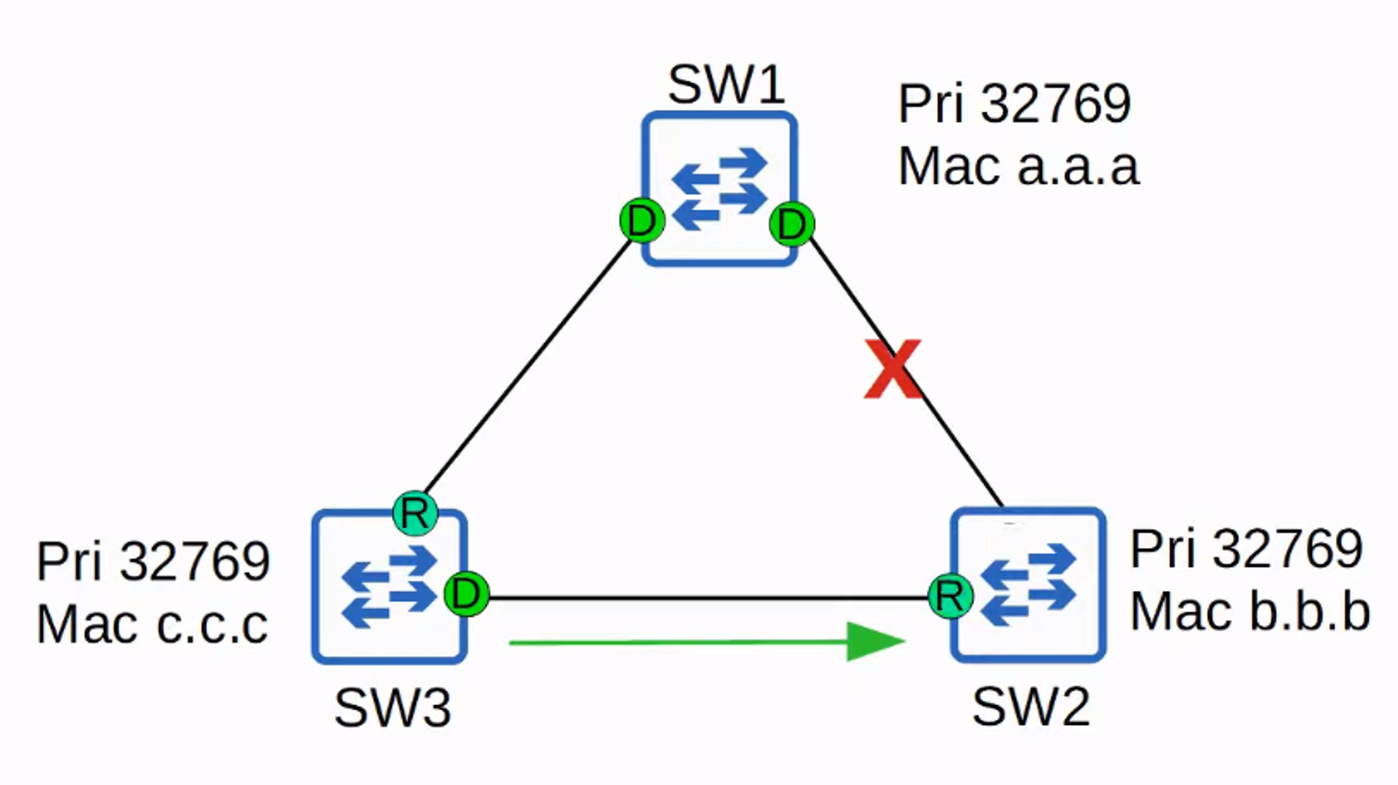
- Alternate Port: In RSTP, an alternate port is a discarding port that receives a superior BPDU from another switch. This is similar to blocking ports in classic STP.
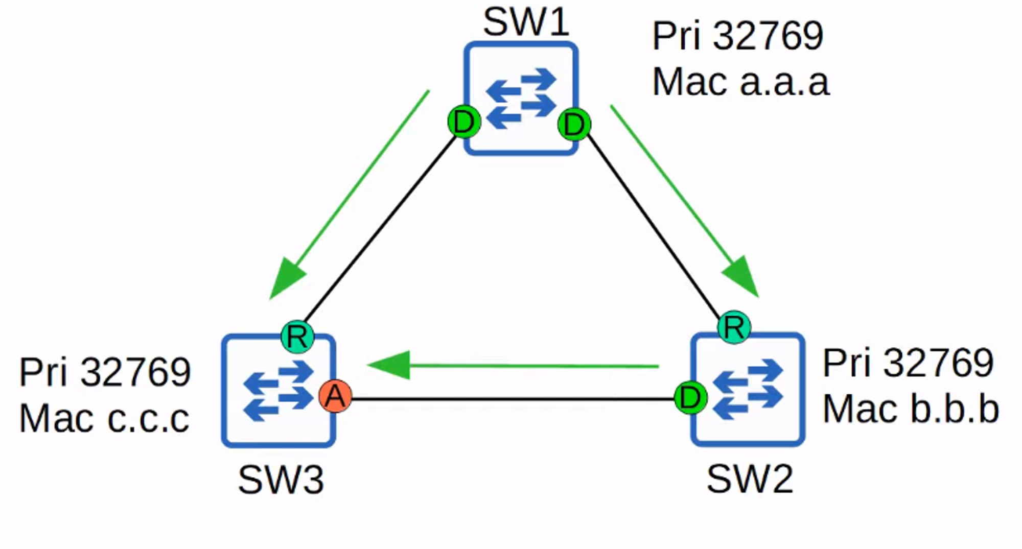
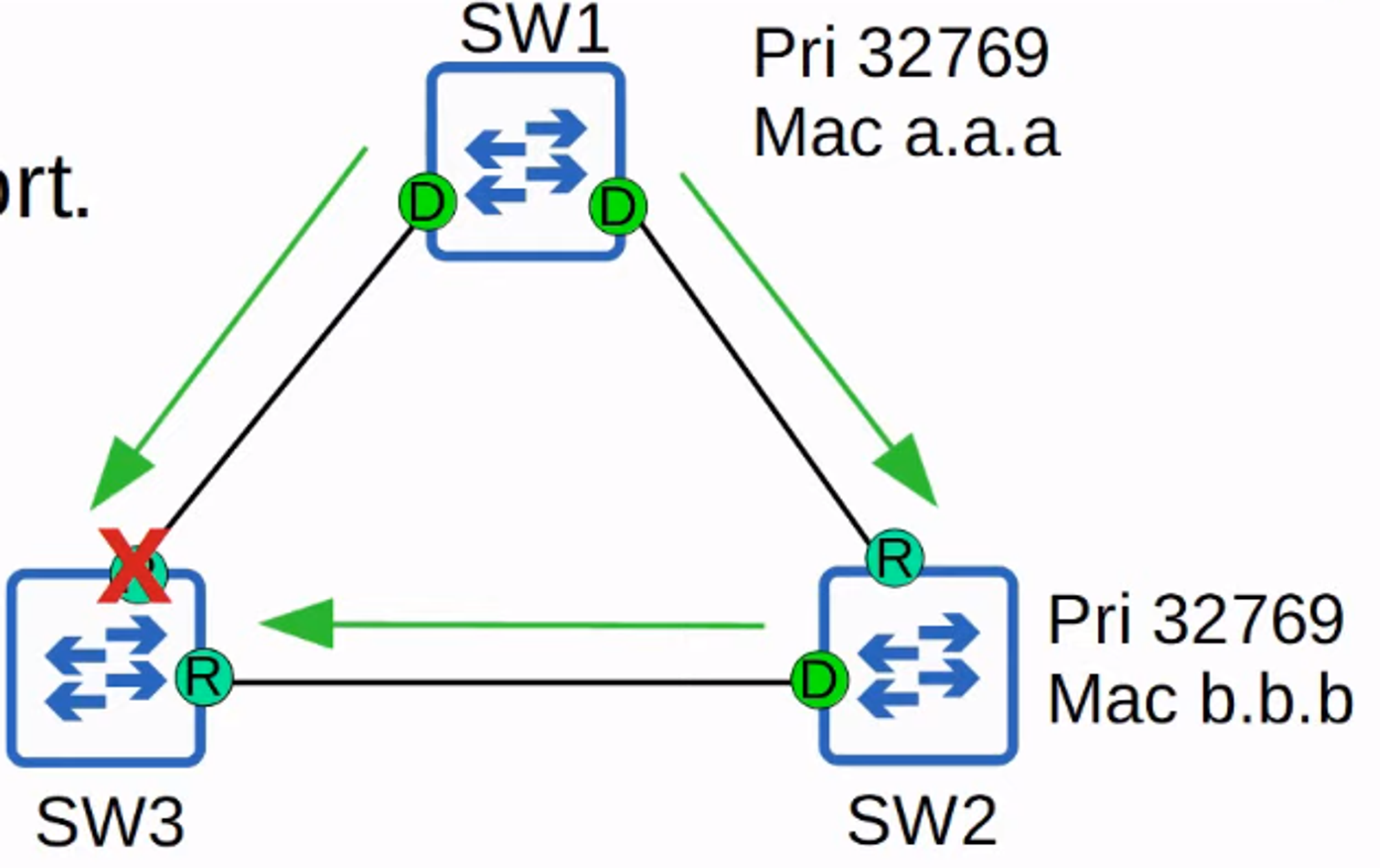
- An alternate port (labeled “A” above) serves as a backup to the root port. If the root port fails, the switch can immediately transition the best alternate port to forwarding.
💡 UplinkFast is an optional feature in classic STP that is built into RSTP. Therefore, you don’t need to enable UplinkFast separately when using RSTP/Rapid PVST+.
RSTP: BackboneFast
- BackboneFast: This feature allows switches to expire the Max Age timers on its interfaces and quickly forward superior BPDUs. It is built into RSTP and does not require separate configuration.
Summary of UplinkFast and BackboneFast
💡 UplinkFast and BackboneFast are optional features in classic STP that must be configured. In RSTP, these features are built-in and operate by default. Understanding their basic purpose (helping blocking/discarding ports move to forwarding rapidly) is sufficient for CCNA preparation.
RSTP: Backup Port Role
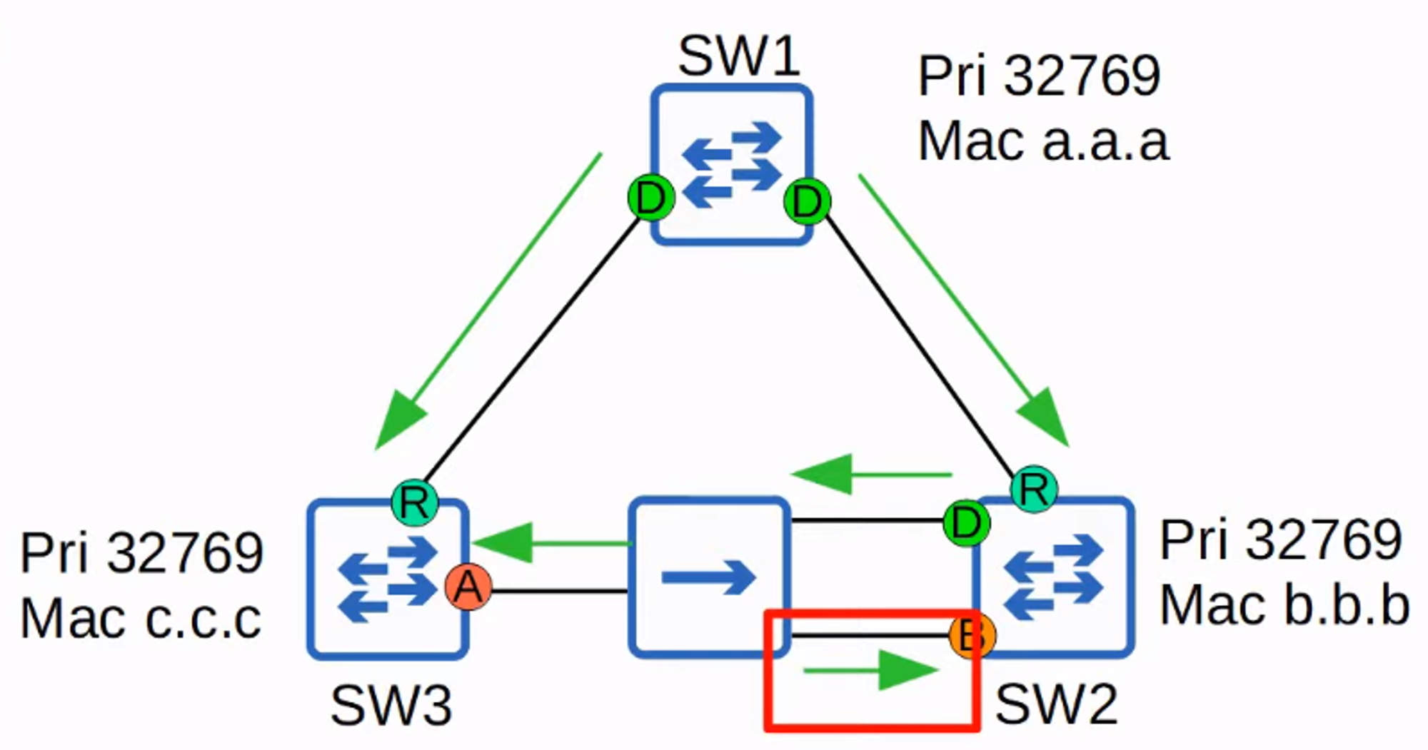
- Backup Port: In RSTP, a backup port is a discarding port that receives a superior BPDU from another interface on the same switch. This occurs when two interfaces are connected to the same collision domain (e.g., via a hub). Hubs are rare in modern networks, so you might not encounter RSTP backup ports.
Example Network Topology
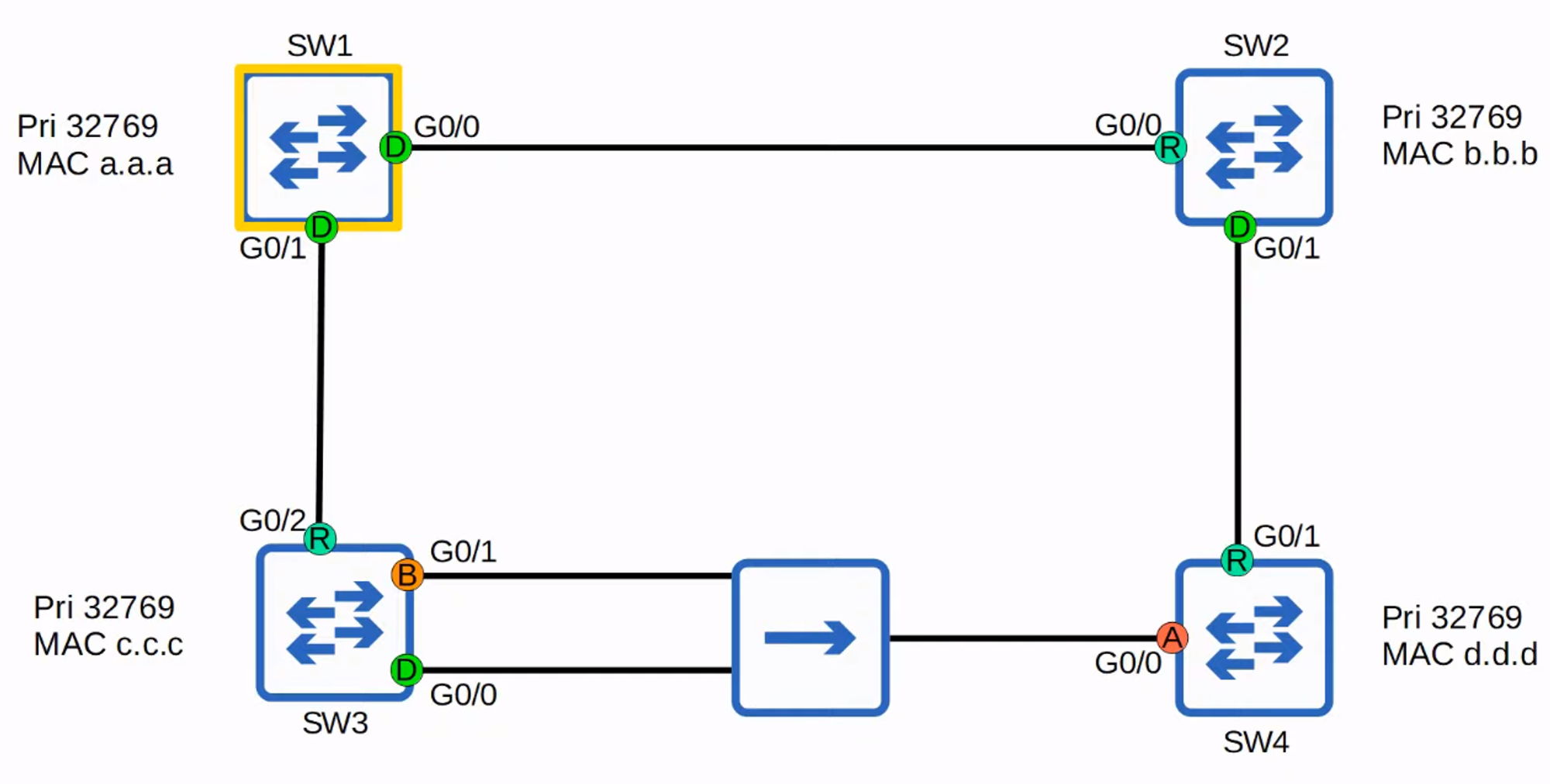
💡 Rapid STP is compatible with classic STP. Interfaces on a Rapid STP-enabled switch connected to a classic STP-enabled switch will operate in classic STP mode (using classic timers and port states).
Rapid STP BPDU
Classic STP vs. Rapid STP BPDU
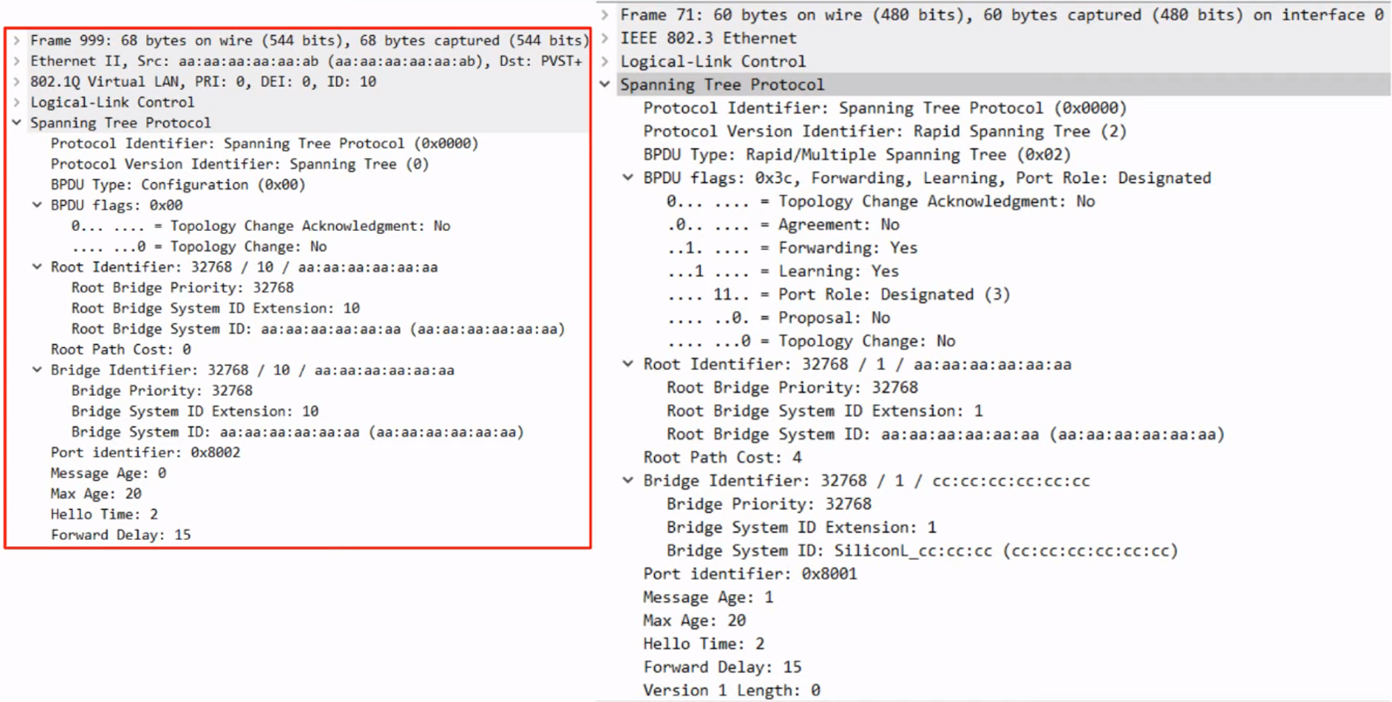
💡 Note:
-
Classic STP BPDU:
- Protocol Version Identifier: Spanning Tree (0)
- BPDU Type: Configuration (0x00)
- BPDU Flags: 0x00
-
Rapid STP BPDU:
- Protocol Version Identifier: Spanning Tree (2)
- BPDU Type: Configuration (0x02)
- BPDU Flags: 0x3c
In classic STP, only the root bridge originates BPDUs, and other switches forward received BPDUs. In Rapid STP, all switches originate and send their own BPDUs from their designated ports.
Rapid Spanning Tree Protocol Overview
- BPDU Transmission: All switches running Rapid STP send their own BPDUs every “hello” time (2 seconds).
- BPDU Aging: Switches age BPDU information more quickly:
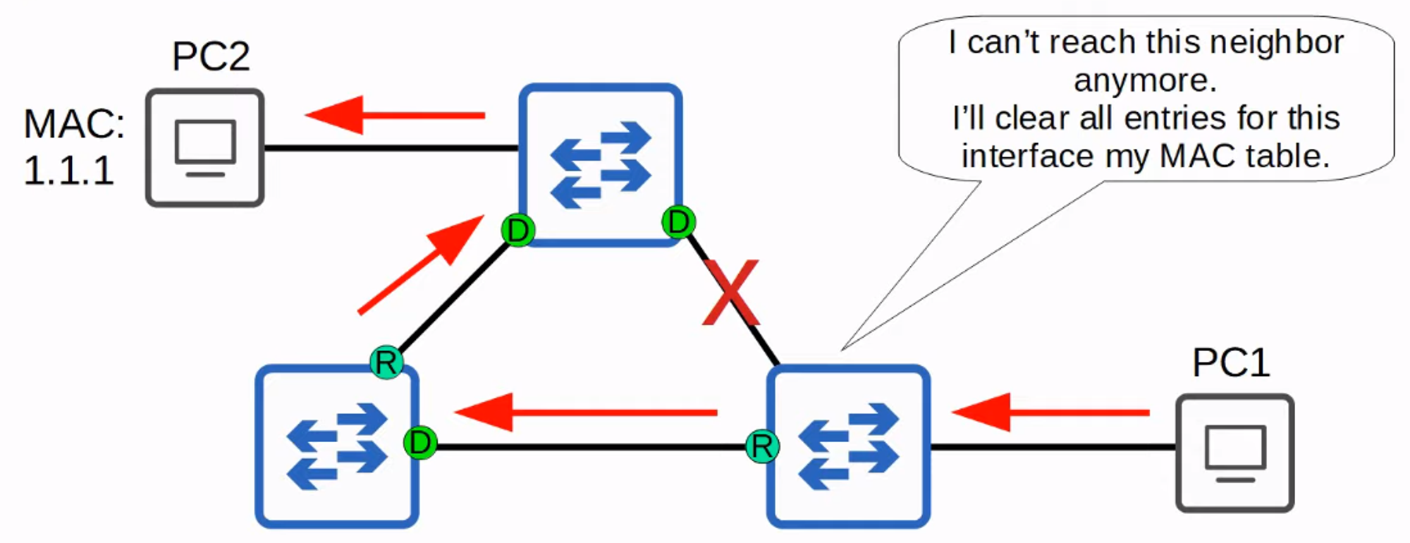
- In classic STP, a switch waits 10 “hello” intervals (20 seconds) before considering a neighbor lost.
- In Rapid STP, a switch considers a neighbor lost if it misses 3 BPDUs (6 seconds), leading to the flushing of all MAC addresses learned on that interface.
RSTP Link Types
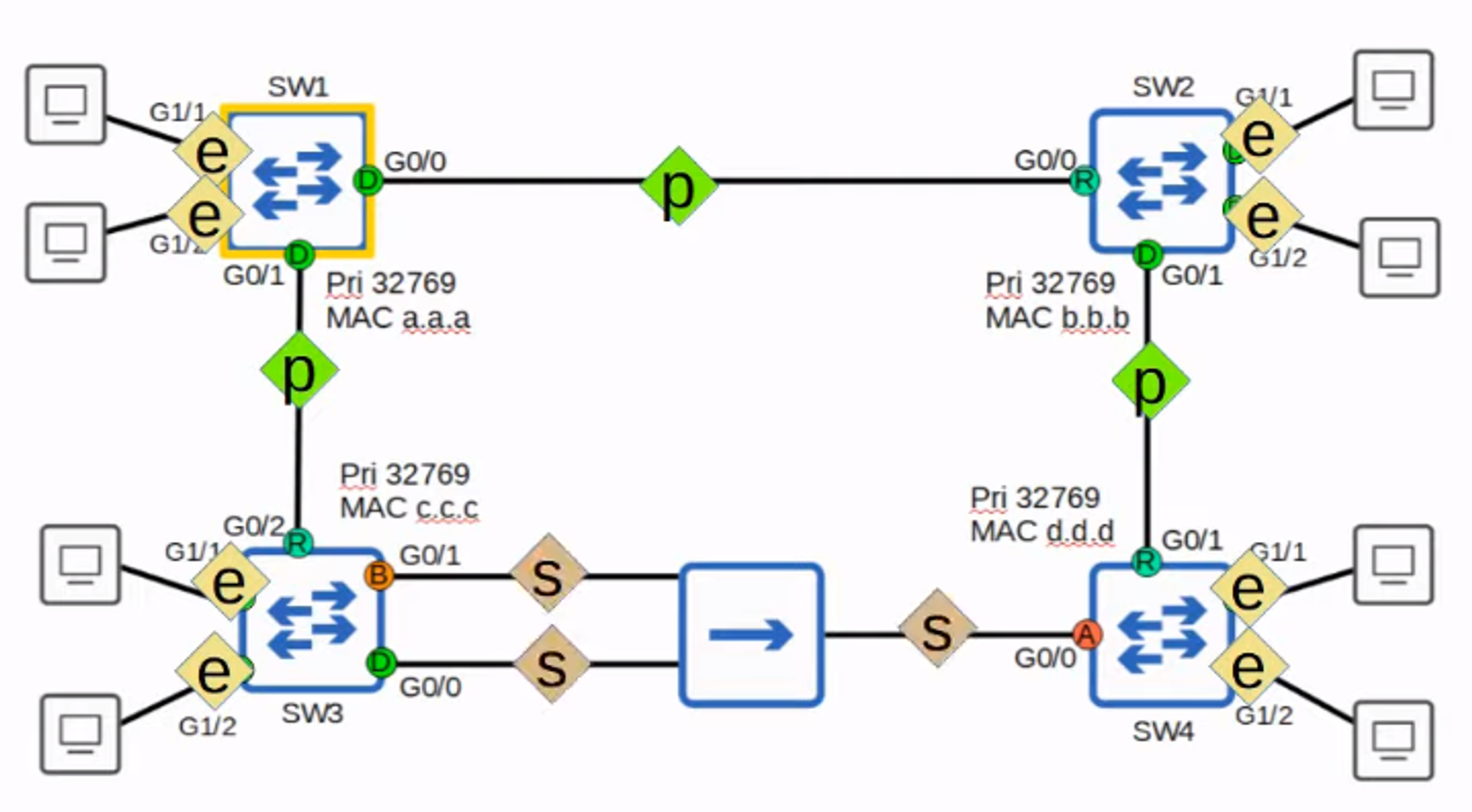
-
Edge Ports: Connected to end hosts and can move straight to the forwarding state without negotiation. They operate like classic STP ports with PortFast enabled.
💡 Configure Edge Ports:
SW1(config-if)# spanning-tree portfast -
Point-to-Point Ports: Connect directly to another switch and function in full-duplex. The interface is automatically detected.
💡 Configure Point-to-Point Ports:
SW1(config-if)# spanning-tree link-type point-to-point -
Shared Ports: Connect to other switches via a hub and function in half-duplex. The interface is automatically detected.
💡 Configure Shared Ports:
SW1(config-if)# spanning-tree link-type shared
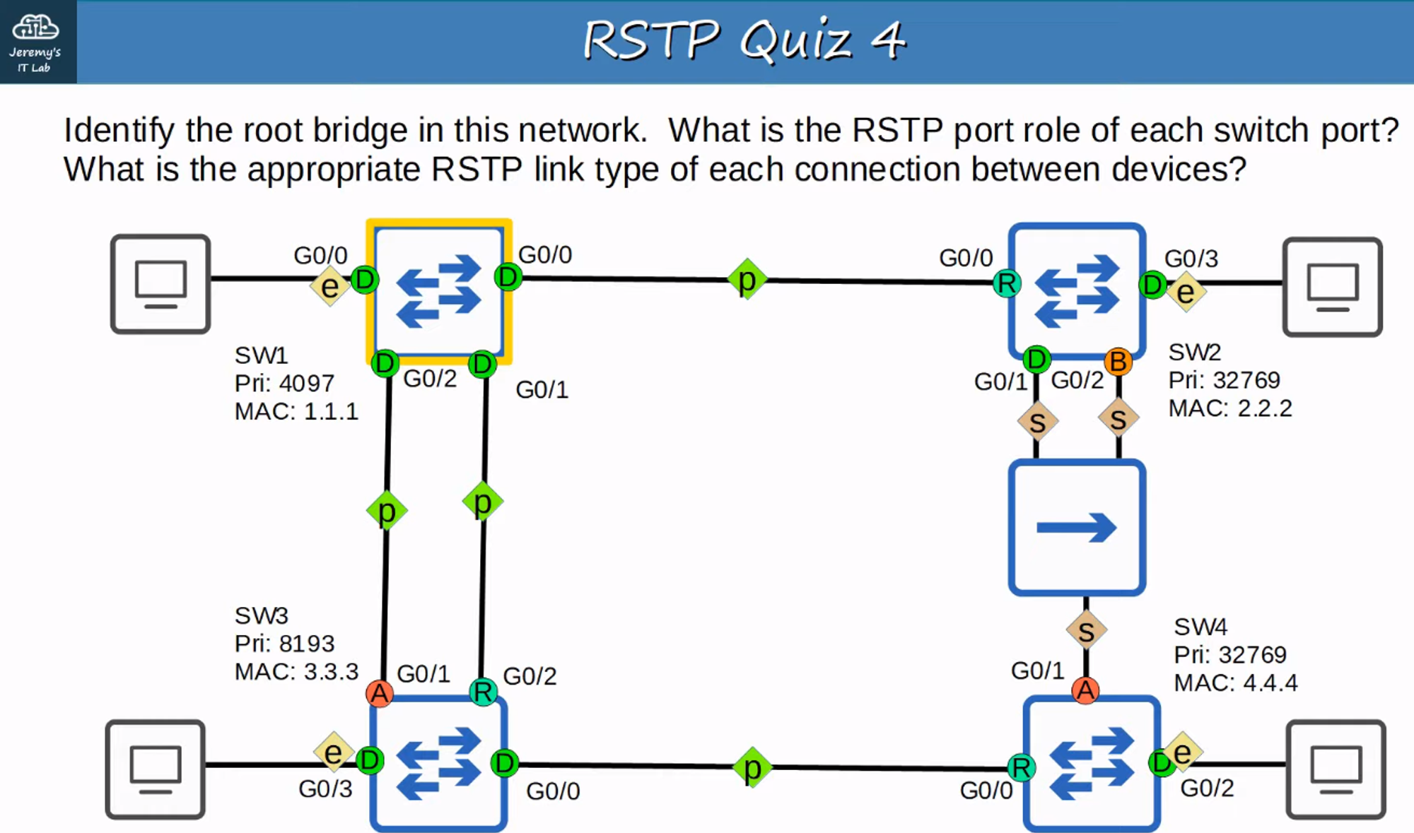
Quiz
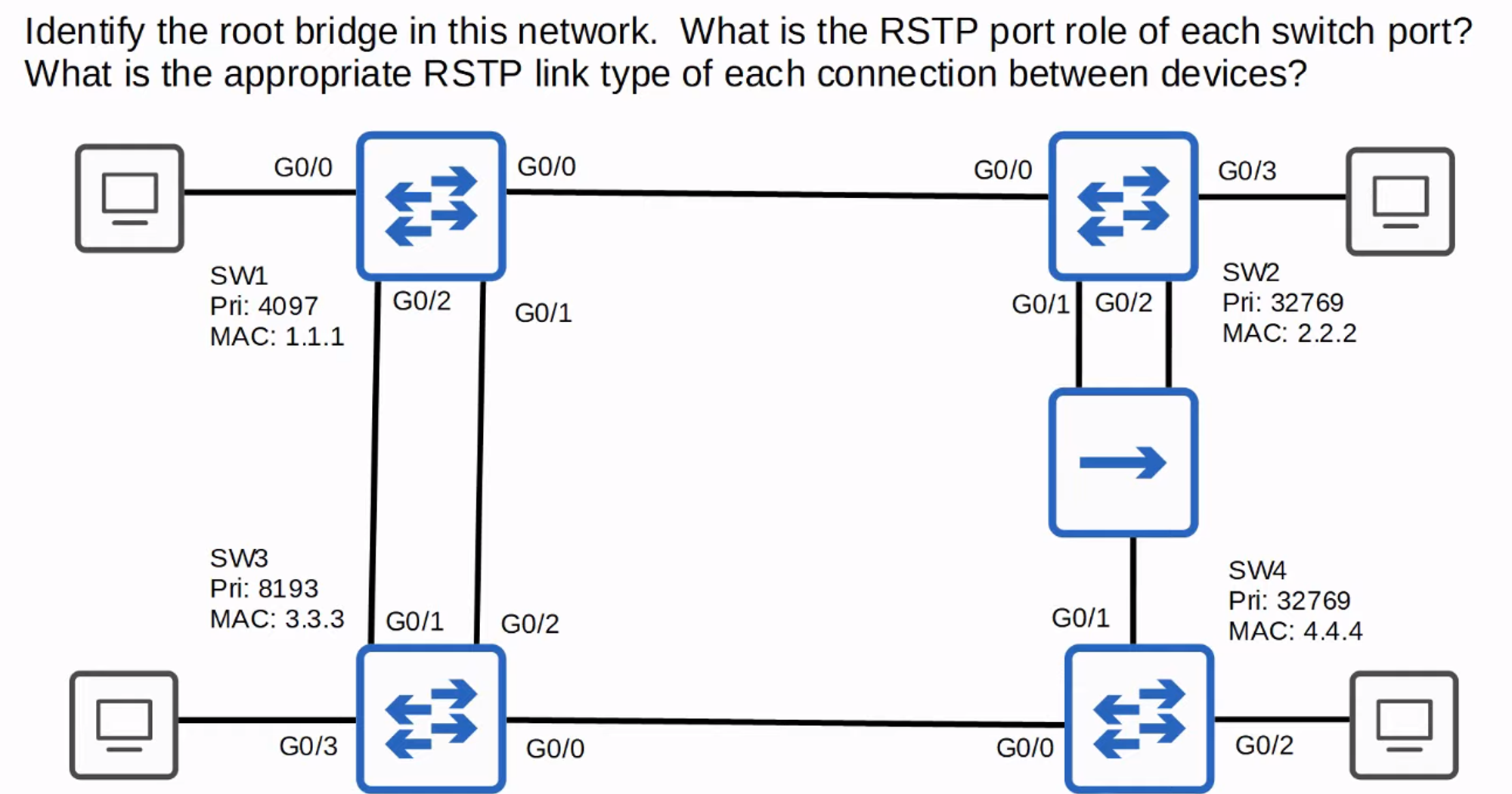
SW1:
- Root Bridge
- G0/0 - 0/3 = Designated
SW2:
- G0/0 = Root Port
- G0/1 = Designated Port
- G0/2 = Backup Port
- G0/3 = Designated Port
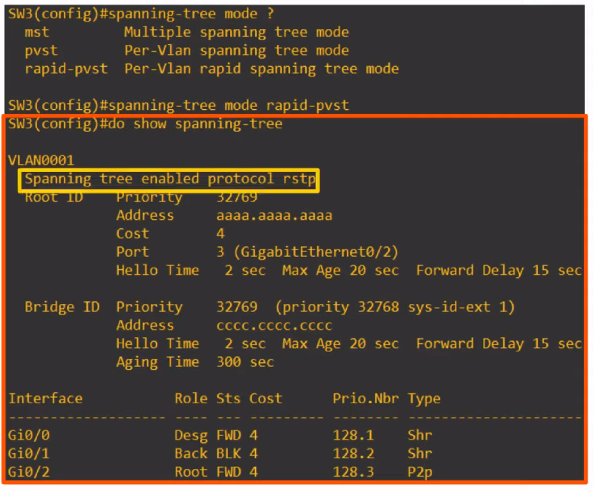
SW3:
- G0/0 = Designated Port
- G0/1 = Alternate Port
- G0/2 = Root Port
- G0/3 = Designated Port
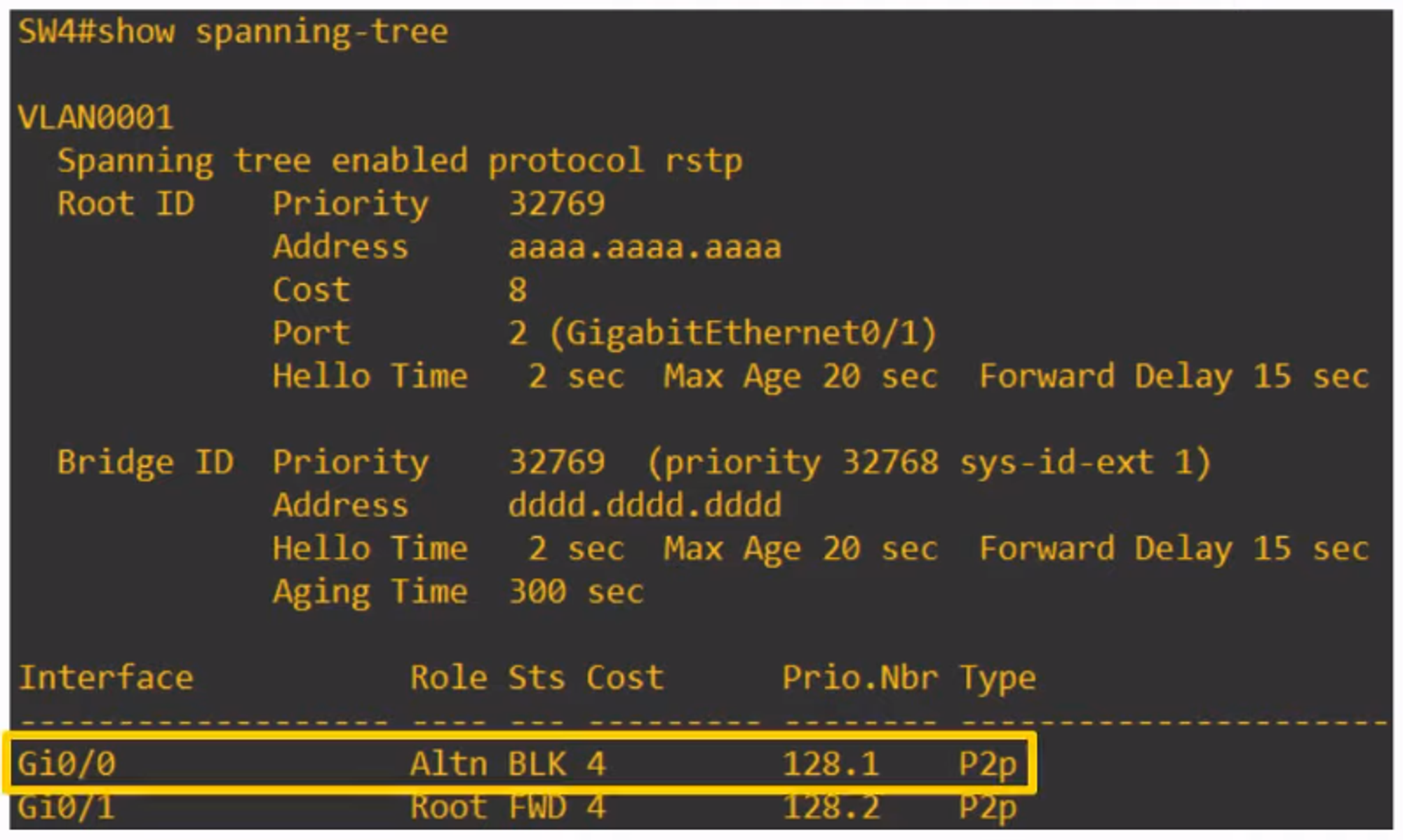
SW4:
- G0/0 = Root
- G0/1 = Alternate Port
- G0/2 = Designated Port
Connections:
- SW1 G0/0 to SW2 G0/0 = Point-to-Point
- SW3 G0/0 to SW4 G0/0 = Point-to-Point
- SW1 G0/1 and G0/2 to SW3 G0/1 and G0/2 = Point-to-Point
- Connections to all end hosts = Edge
- Connection from SW4 to Hub = Shared
- Connections from SW2 to Hub = Shared
Answer: