Redundancy in Networks
- Redundancy is critical in modern network design to ensure continuous availability.
- Networks are expected to operate 24/7/365, and even brief downtimes can be detrimental to business operations.
- Redundancy ensures that if one network component fails, other components can take over seamlessly, minimizing or eliminating downtime.
Poor Network Design Example
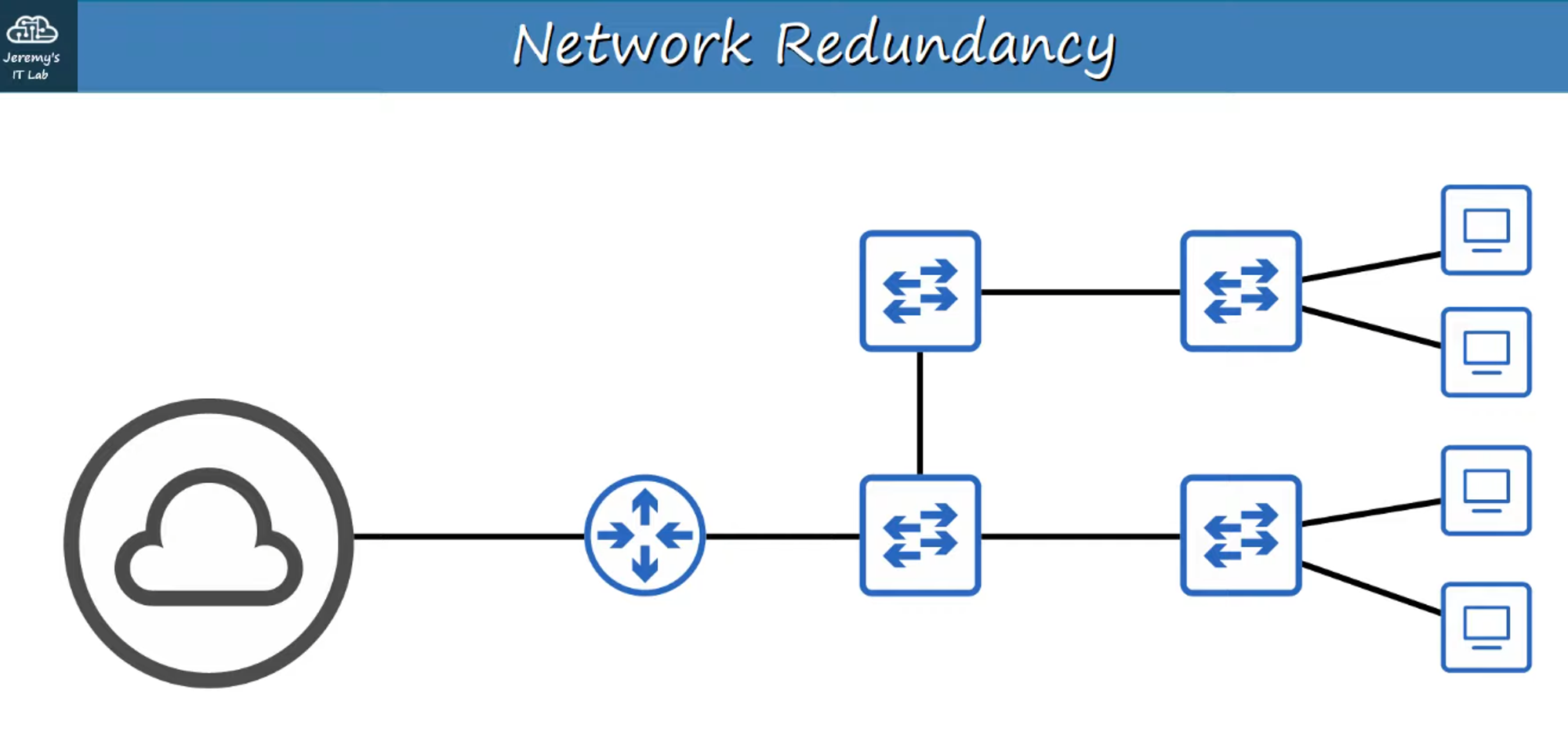
- This design has multiple single points of failure, where a single failure could disrupt the entire network.
Improved Network Design
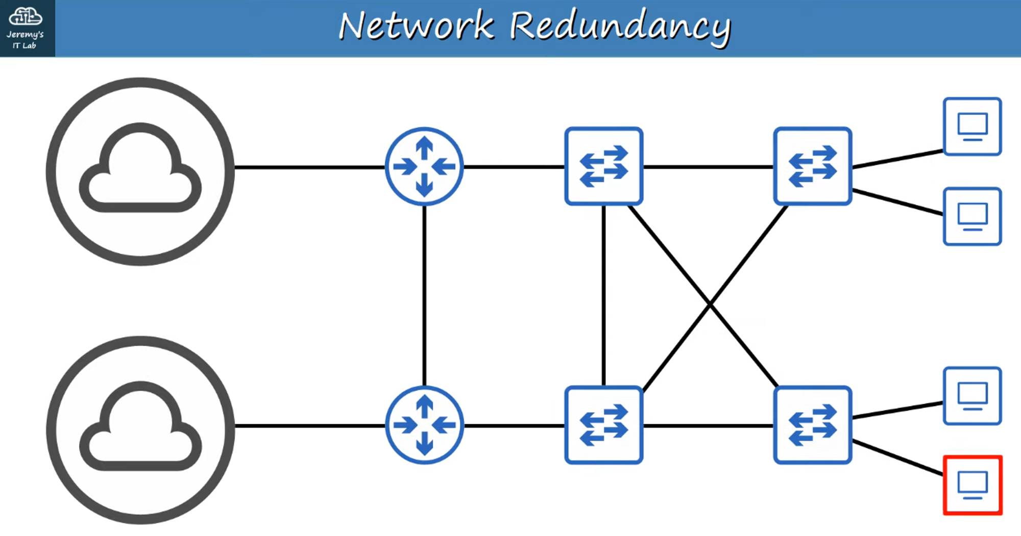
- This design incorporates redundancy, ensuring that failure in one component does not bring down the entire network.
The Downside of Redundancy: Broadcast Storms
While redundancy is beneficial, it can lead to Layer 2 loops, causing network issues like broadcast storms.
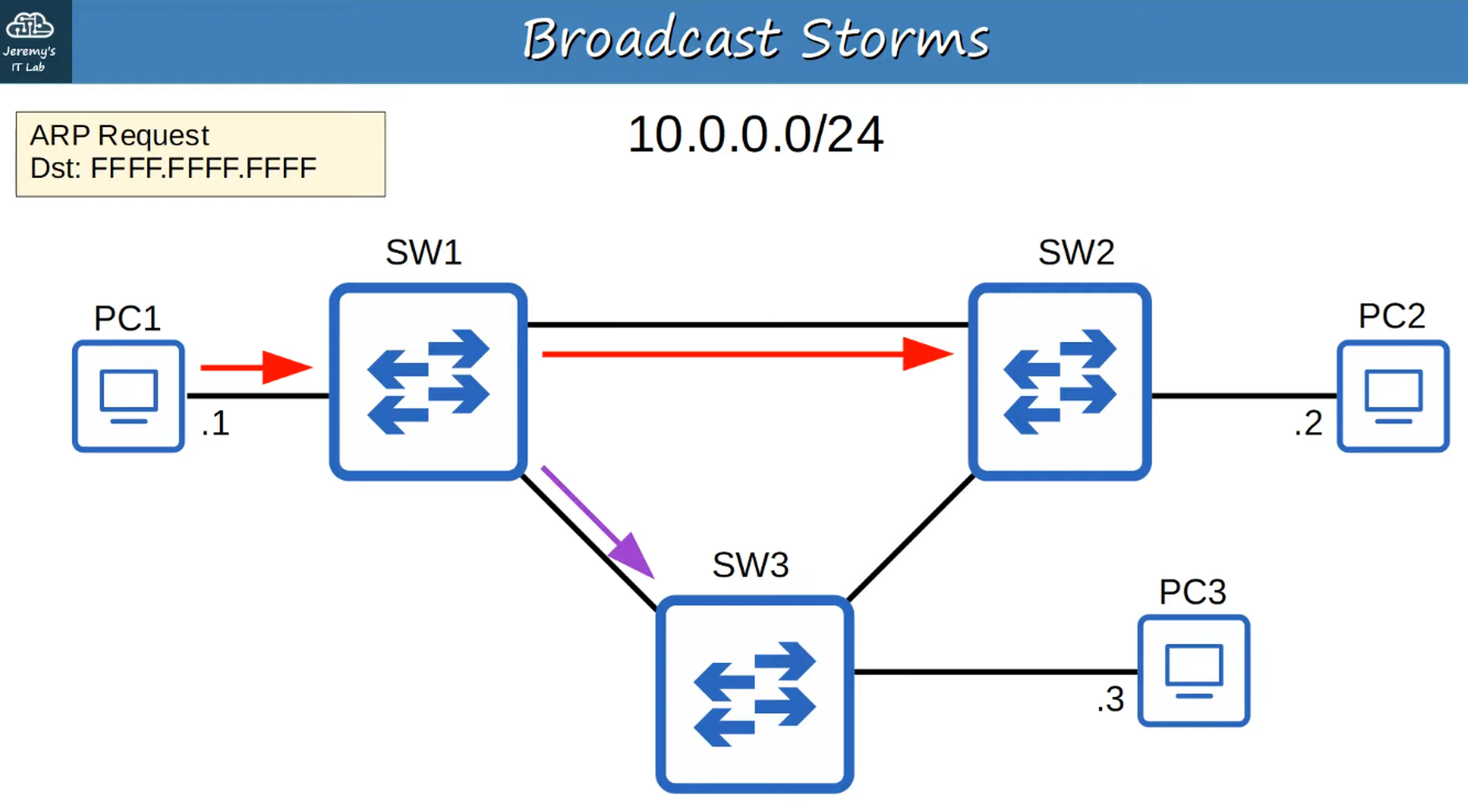
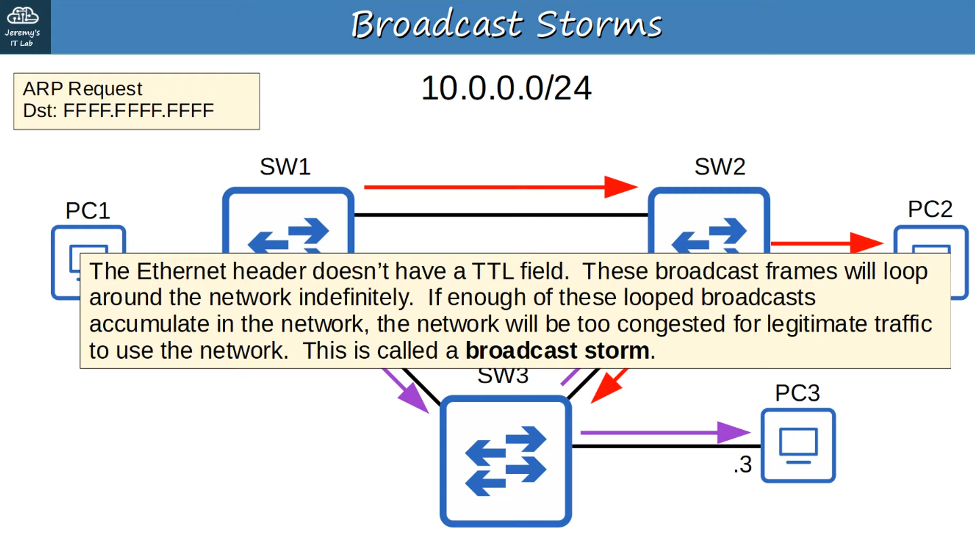
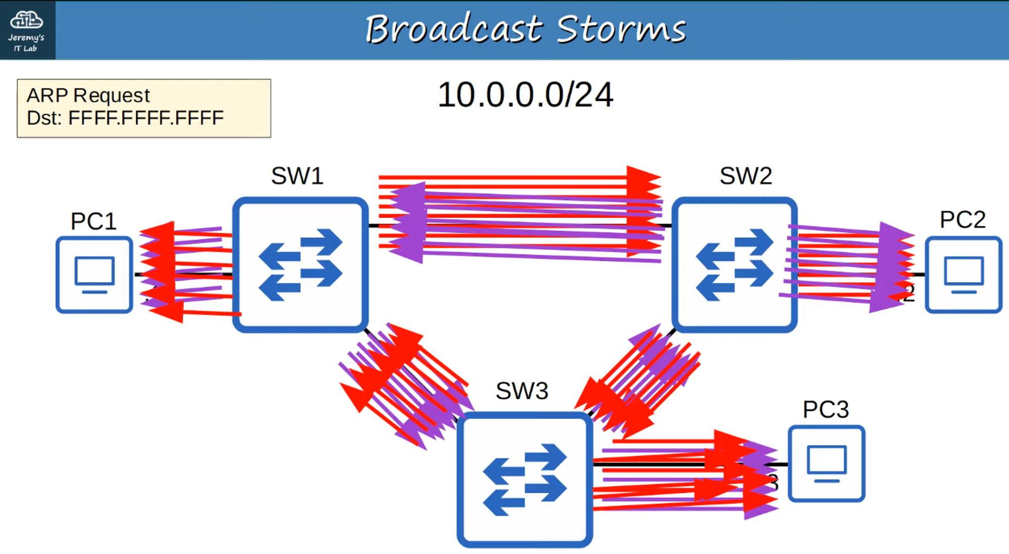
Broadcast Storms
- A broadcast storm occurs when broadcast frames circulate endlessly in a loop, causing network congestion.
- The excessive traffic can overwhelm network resources, leading to significant degradation in performance.
MAC Address Flapping
- MAC Address Flapping happens when a switch repeatedly updates its MAC address table because the same source MAC address is detected on different ports due to loops.
- This constant updating can cause instability in the network.
Spanning Tree Protocol (STP): 802.1D
To prevent Layer 2 loops in a network with redundant paths, we use the Spanning Tree Protocol (STP).
What is STP?
- STP is defined in the IEEE 802.1D standard.
- It prevents Layer 2 loops by placing redundant ports in a blocking state, essentially disabling those interfaces until needed.
- If an active forwarding interface fails, the blocked ports can switch to a forwarding state to maintain connectivity.
- Ports in the blocking state only send or receive STP messages, known as Bridge Protocol Data Units (BPDUs).
Note: STP still uses the term “bridge,” which historically referred to devices used to connect network segments. In modern networks, switches fulfill this role.
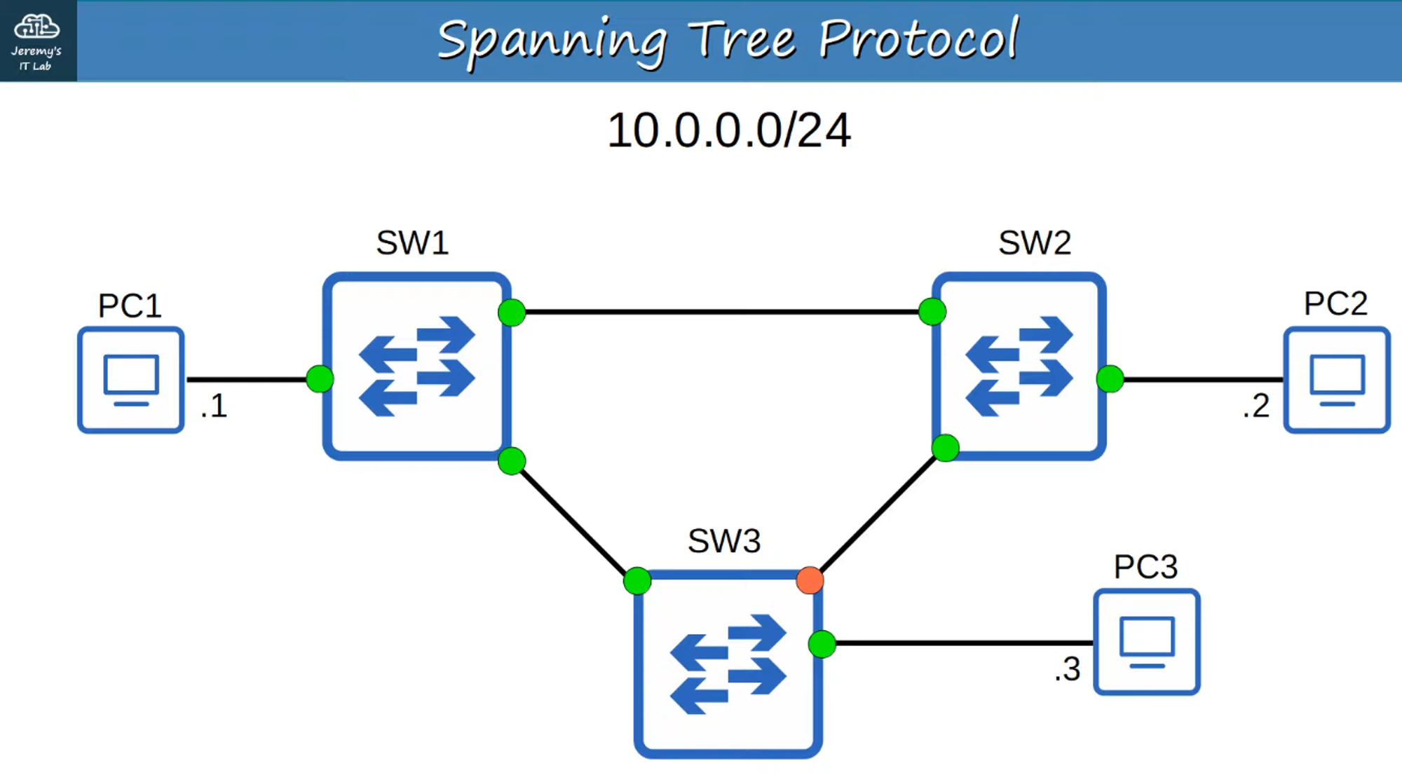
- The orange interface is blocked, breaking the loop and preventing broadcast storms and MAC address flapping.
How STP Works
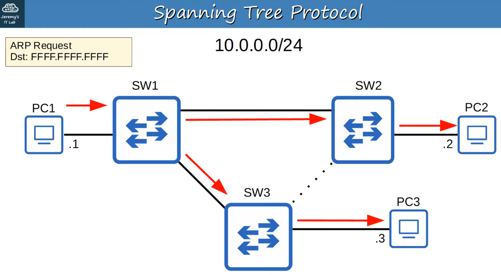
- STP selects which ports should be forwarding and which should be blocking to create a single, loop-free path through the network.
- STP-enabled switches send and receive Hello BPDUs out of all interfaces, typically once every two seconds per interface.
- If a switch receives a Hello BPDU on an interface, it knows that the interface is connected to another switch (since routers, PCs, etc., do not use STP and therefore do not send Hello BPDUs).
BPDU and Root Bridge Election
BPDUs contain crucial information used by switches to elect a Root Bridge for the network.
- The switch with the lowest Bridge ID becomes the Root Bridge.
- All ports on the Root Bridge are placed in a forwarding state, while other switches in the topology must establish a path to the Root Bridge.
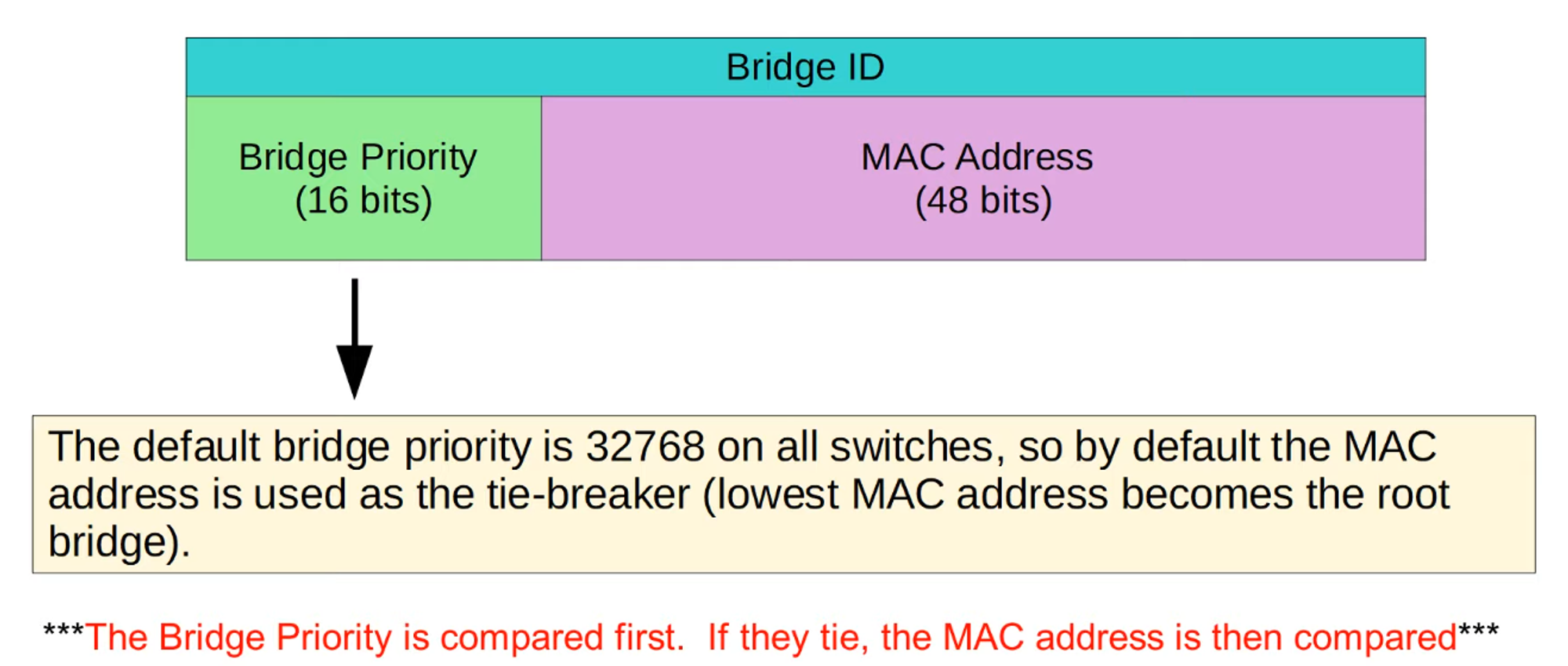
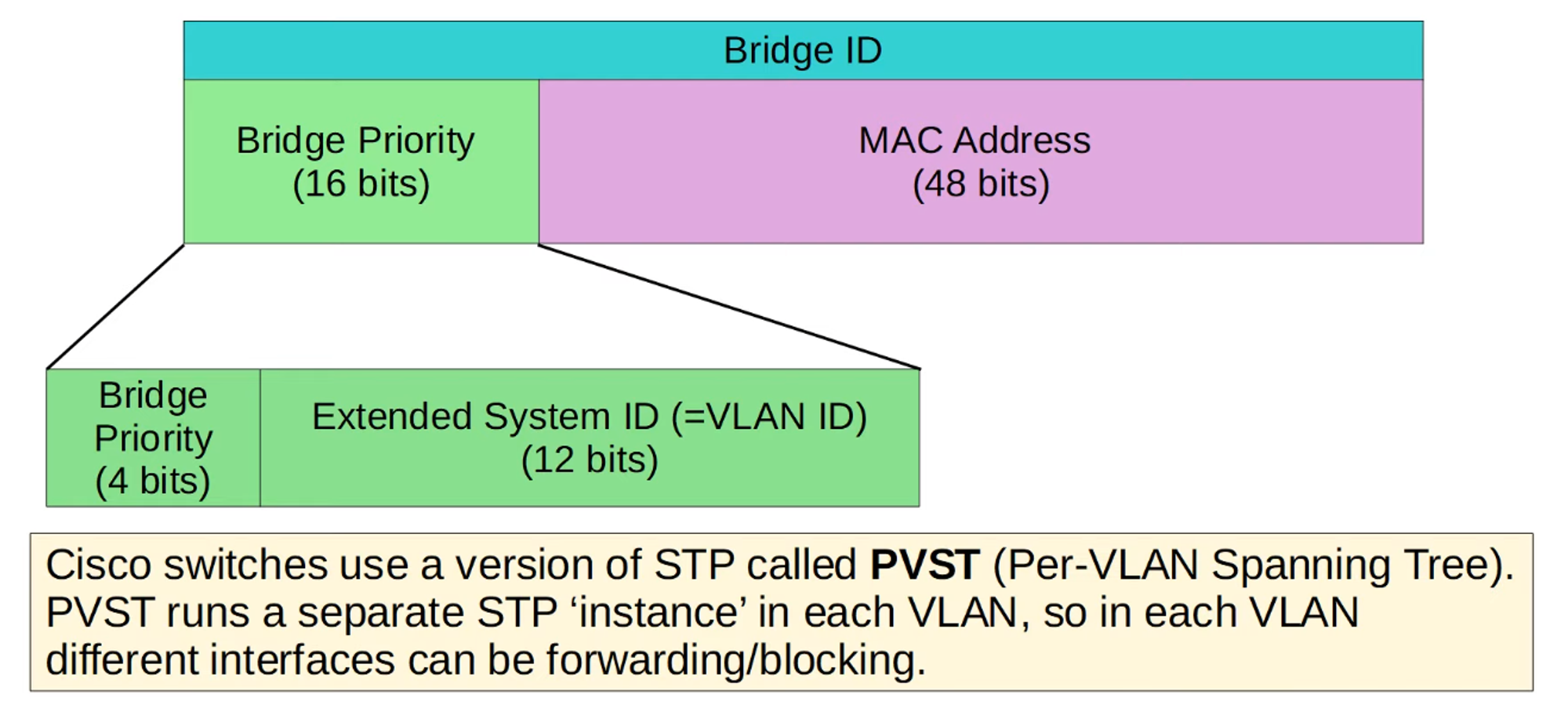
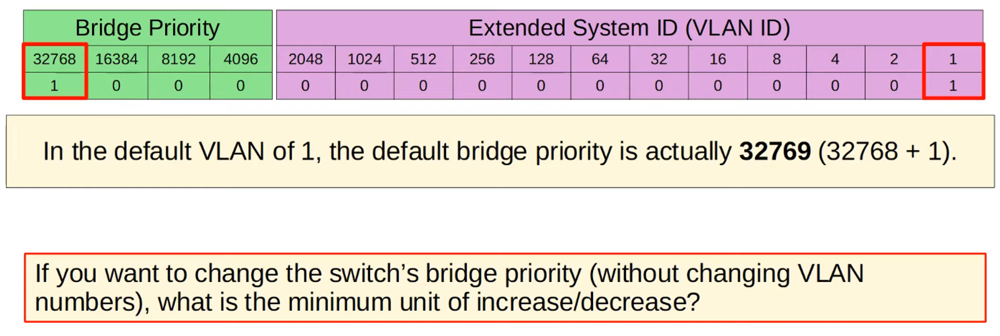
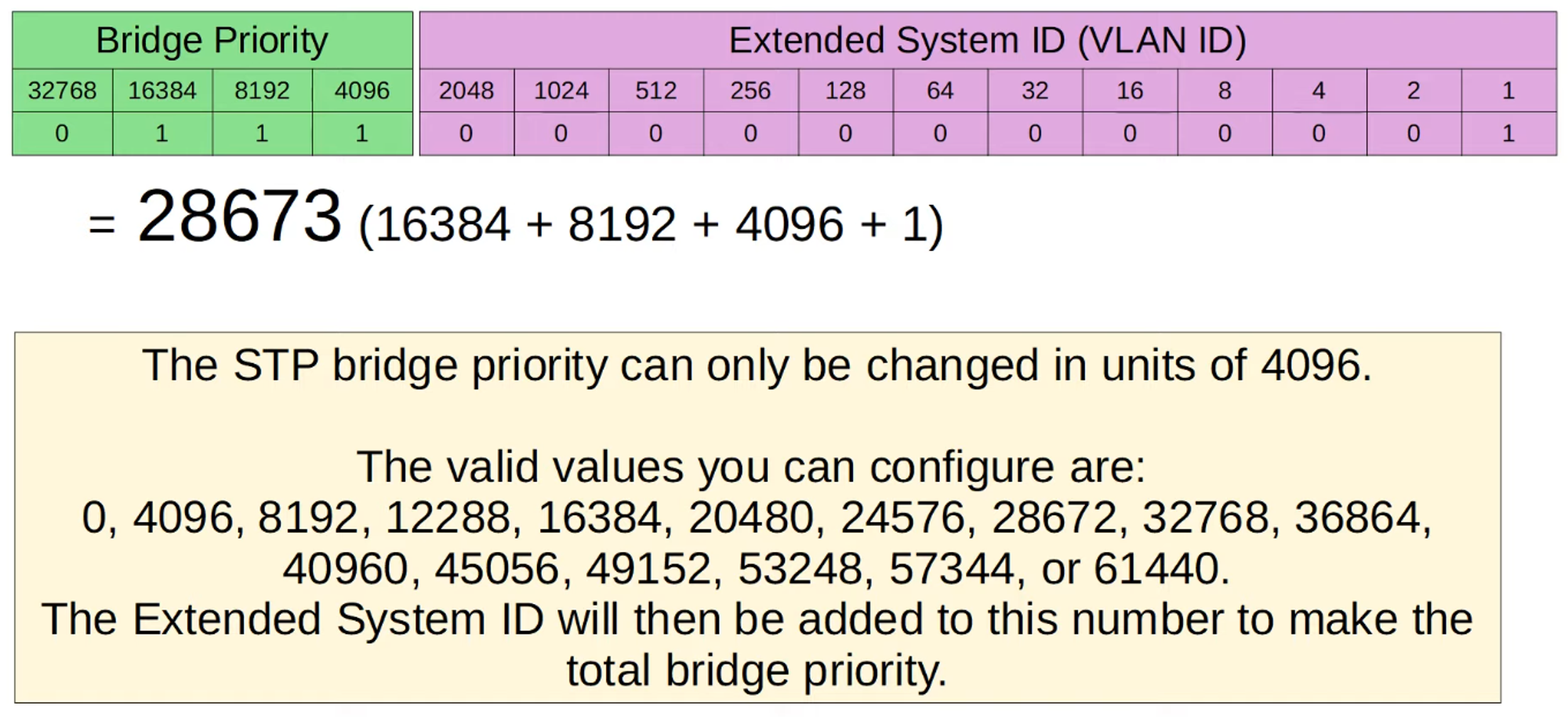
Bridge Priority
- Bridge Priority can be adjusted in increments of 4096 to influence which switch becomes the Root Bridge.
- In the example topology, SW1 becomes the Root Bridge due to its MAC address being the lowest.
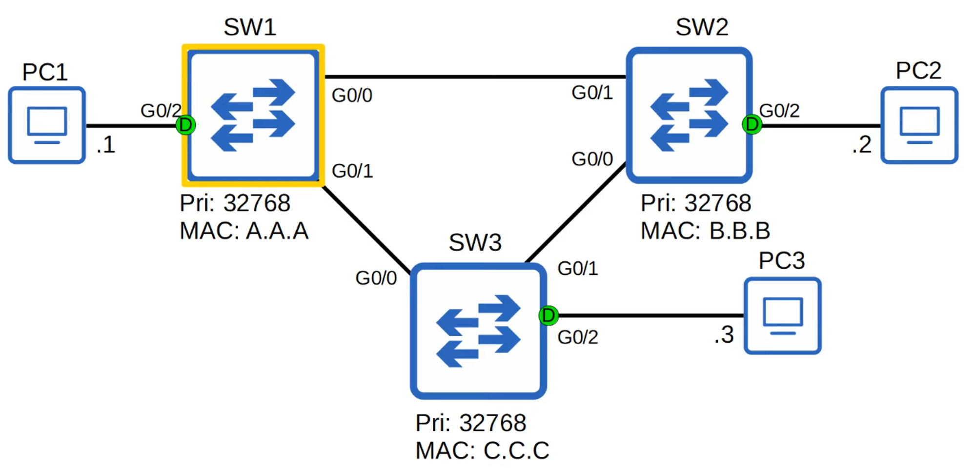
- All interfaces on the Root Bridge are Designated Ports, which are always in a forwarding state.
STP Steps
-
Root Bridge Election:
- The switch with the lowest Bridge ID becomes the Root Bridge.
- If the Bridge ID is tied, the switch with the lowest MAC address wins.
- All ports on the Root Bridge are Designated Ports in a forwarding state.
-
Root Port Selection:
- Each remaining switch selects one of its interfaces to be its Root Port (the port with the lowest Root Path Cost).
- Ports across from the Root Port on other switches are always Designated Ports.
-
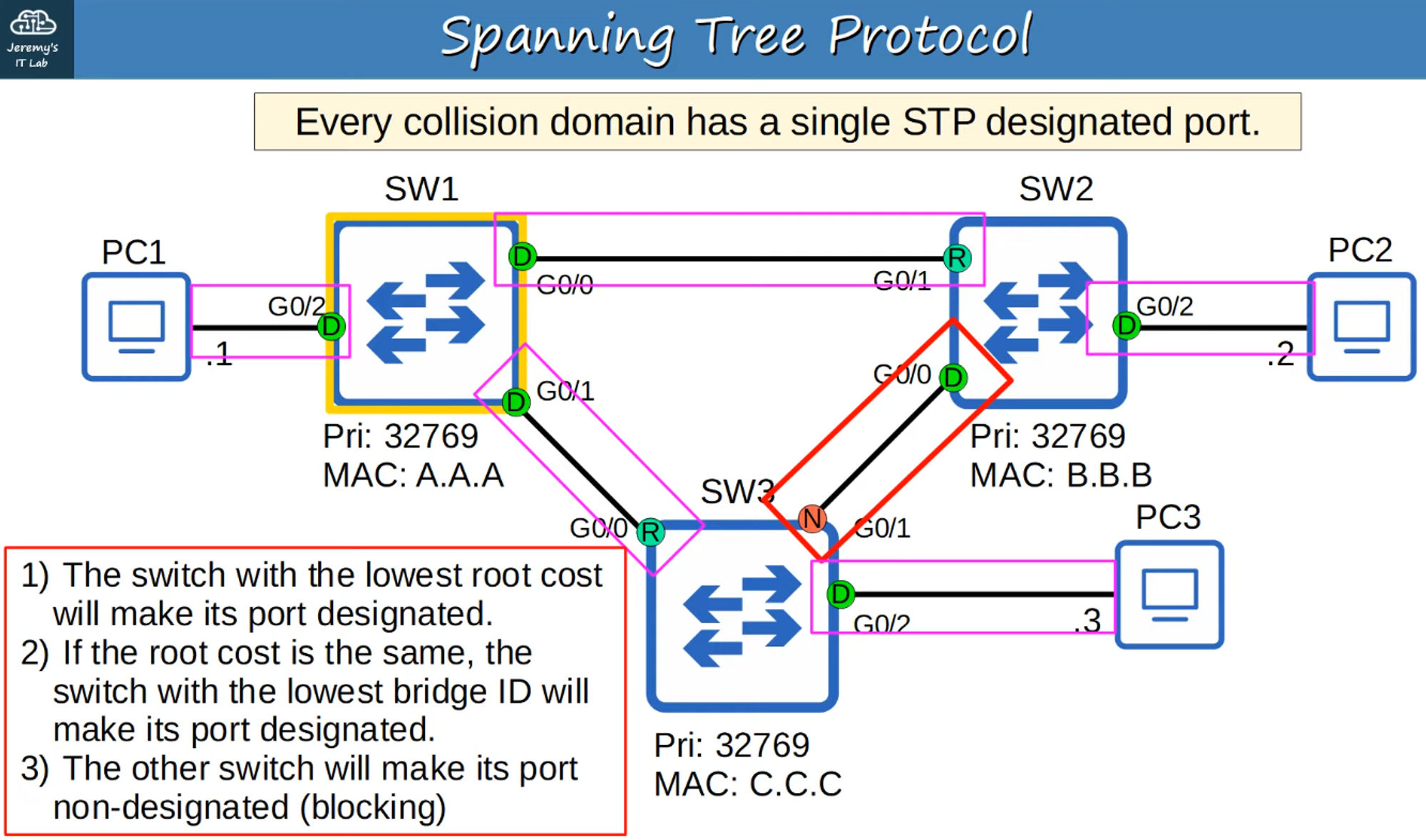
Designated Port Selection:
- In each collision domain, one interface is selected as the Designated Port (forwarding state).
- The other port in the collision domain becomes Non-Designated (blocking state).
STP Cost Chart
- Only outgoing interfaces toward the Root Bridge have an STP cost. The cost is the sum of all outgoing port costs until reaching the Root Bridge.
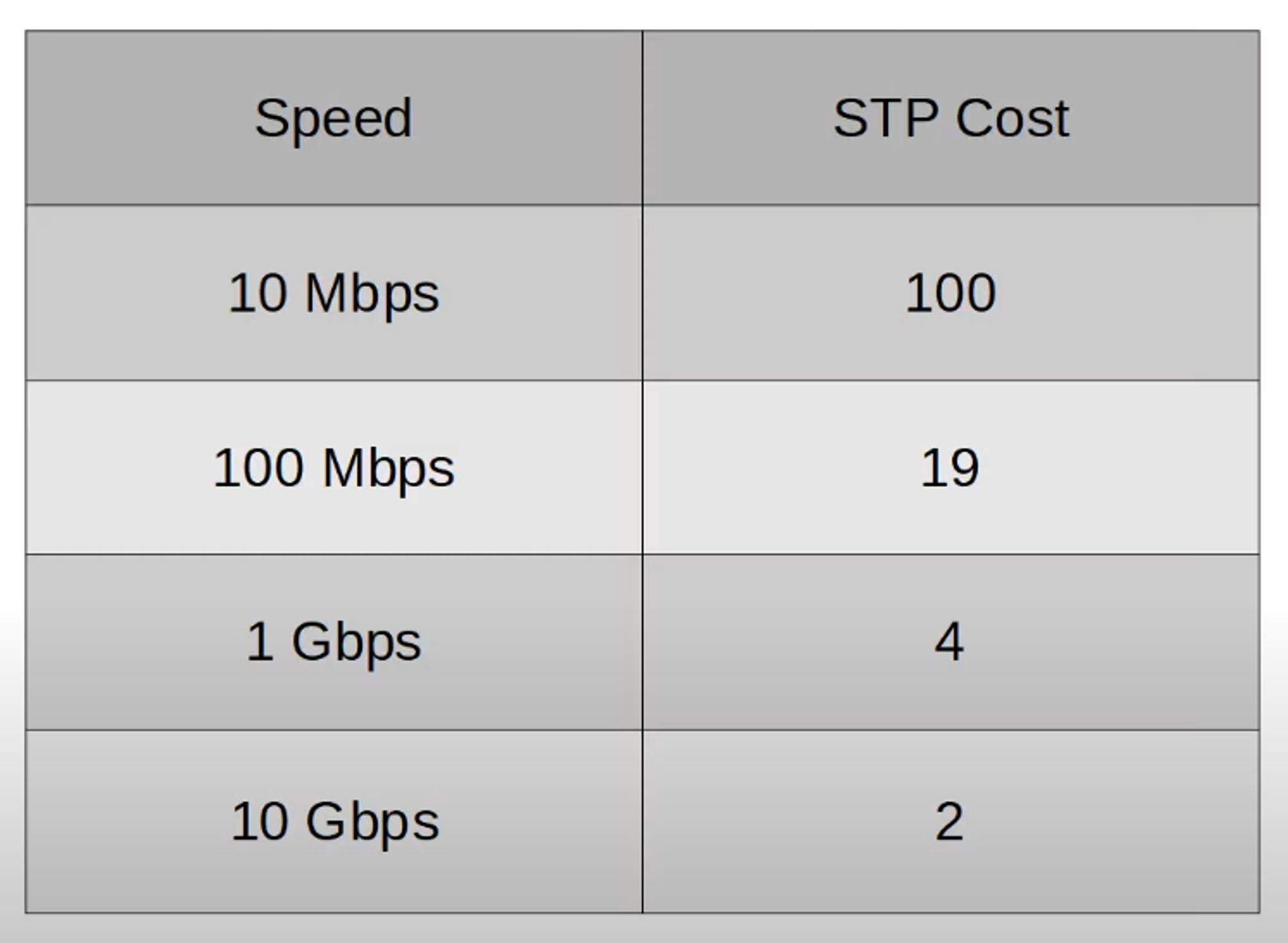
- SW1, as the Root Bridge, has an STP cost of 0 on all interfaces.
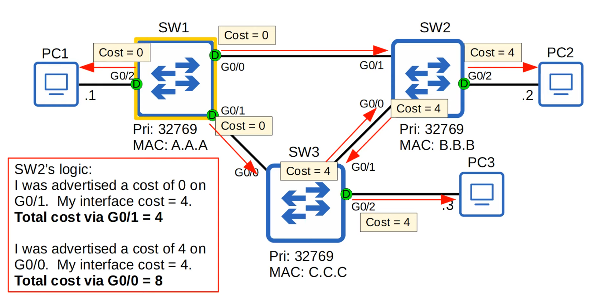
- Ports connected to another switch’s Root Port must be Designated Ports (D).
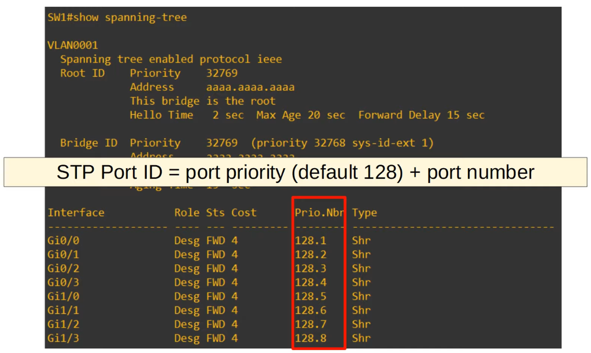
- In case of a tie, the Neighbor Switch Port ID is used as a tiebreaker.
Determining Which Port Will Be Blocked
Quiz: Identify the Root Bridge and Interface Roles
Example 1:
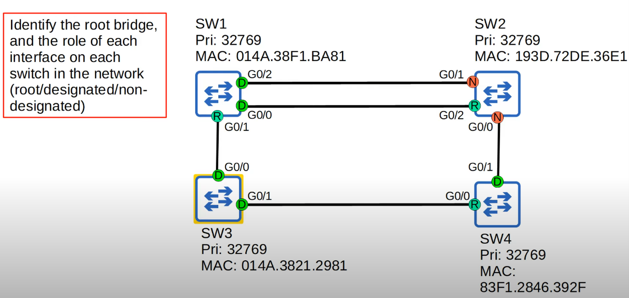
- All switches have the same priority number (32769), so the tiebreaker goes to the switch with the lowest MAC address.
- SW3 has the lowest MAC address, so it becomes the Root Bridge, and all its interfaces become Designated Ports.
- SW1 (G0/1) and SW4 (G0/0) interfaces connected to SW3 become Root Ports.
- Since SW2 has two connections to SW1, SW1’s incoming interfaces both become Designated Ports.
- SW2 (G0/2) becomes a Root Port because SW1’s G0/0 interface has a lower cost than its G0/2 interface.
- The remaining interfaces on SW2 become Non-Designated because it has the highest Root Cost (12), and the interfaces they are connected to on other switches become Designated Ports.
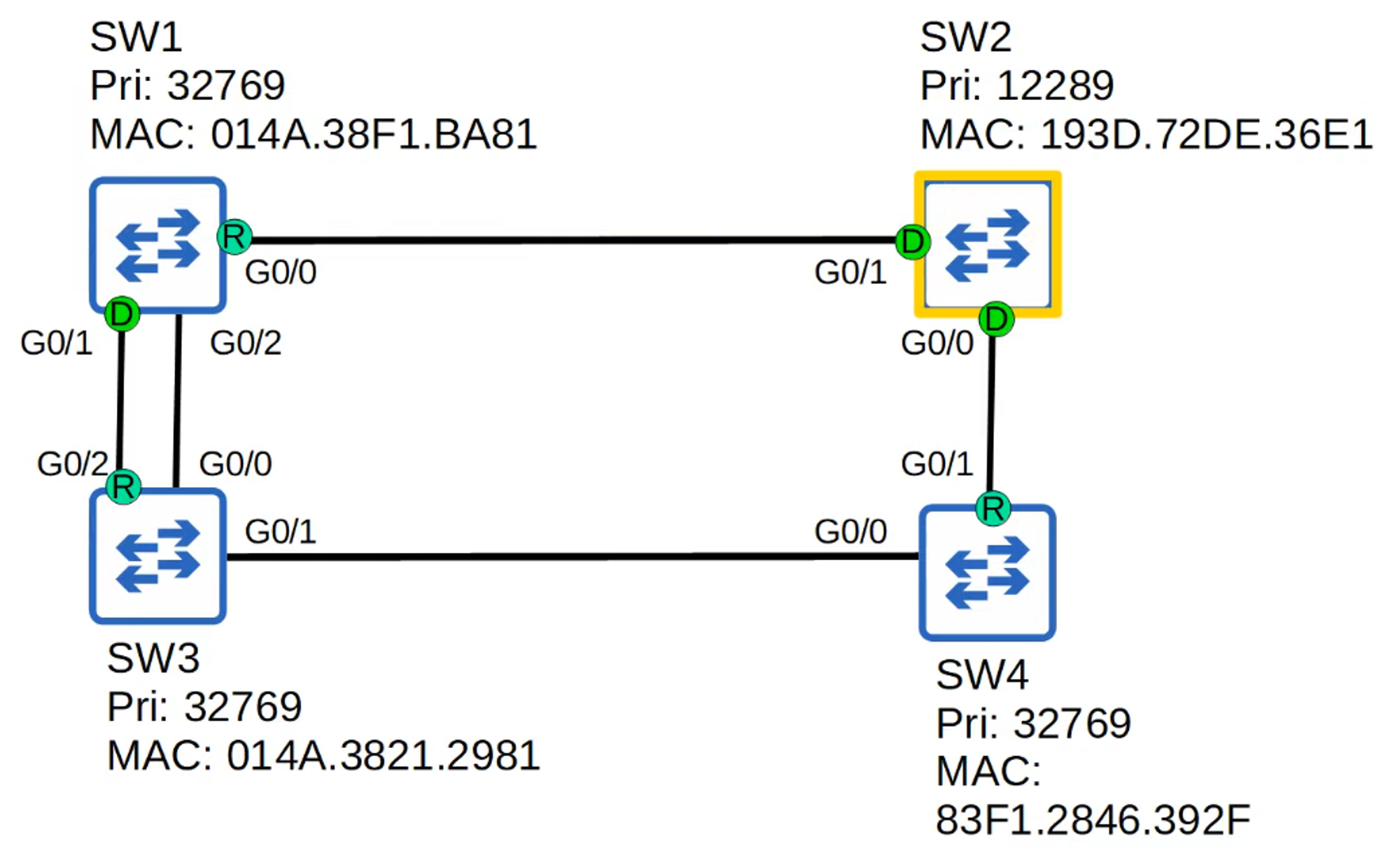
Example 2:
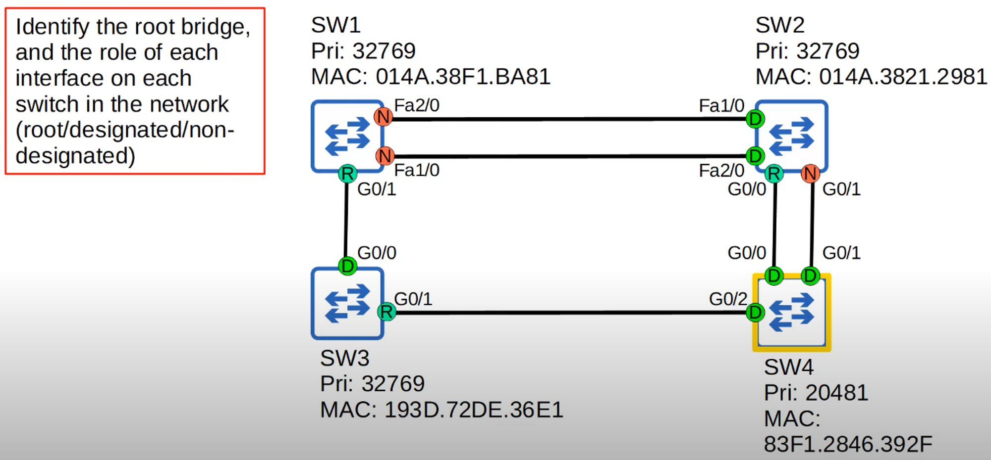
- SW4 has the lowest priority number, so it becomes the Root Bridge, and all its interfaces become Designated Ports.
- SW2 (G0/0) becomes the Root Port because SW4’s G0/0 connection has a lower number than G0/1.
- SW3 (G0/1) becomes the Root Port.
- SW1 (G0/1) becomes the Root Port because G0/1 has a lower cost than Fa1/0 and 2/0.
- The remaining ports on SW1 and SW2 will either be Designated or Non-Designated based on the STP cost and priority.