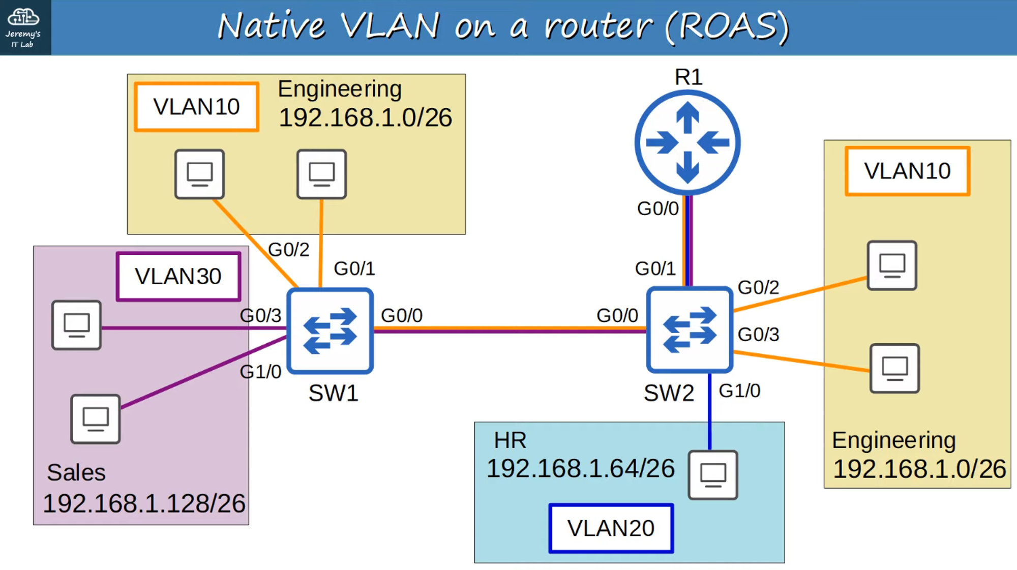
Native VLAN on a Router (ROAS)
-
Native VLAN untagged frames are more efficient and faster than tagged frames because they are smaller in size.
-
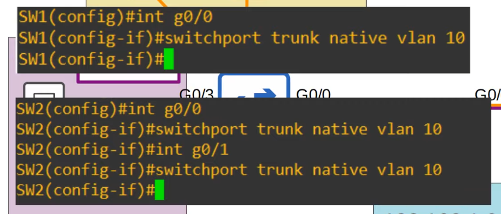
Let’s reset both SW1 and SW2 to native VLAN 10.
Configuring Native VLAN on a Router
There are two methods to configure the native VLAN on a router:
-
Using Sub-Interface:
-
Use the command
encapsulation dot1q <vlan-id>on the router’s sub-interface.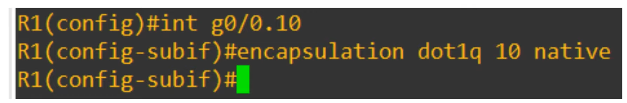
-
-
Using the Physical Interface:
-
Configure the IP address directly on the router’s physical interface.
-
The
encapsulation dot1q <vlan-id>command is not required.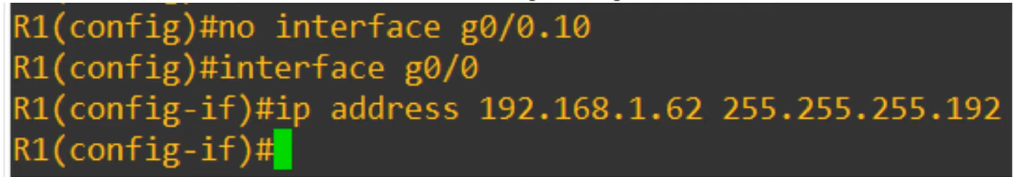
-
Show Running Configuration
-
Example output of the
show running-configcommand for the G0/0 interface: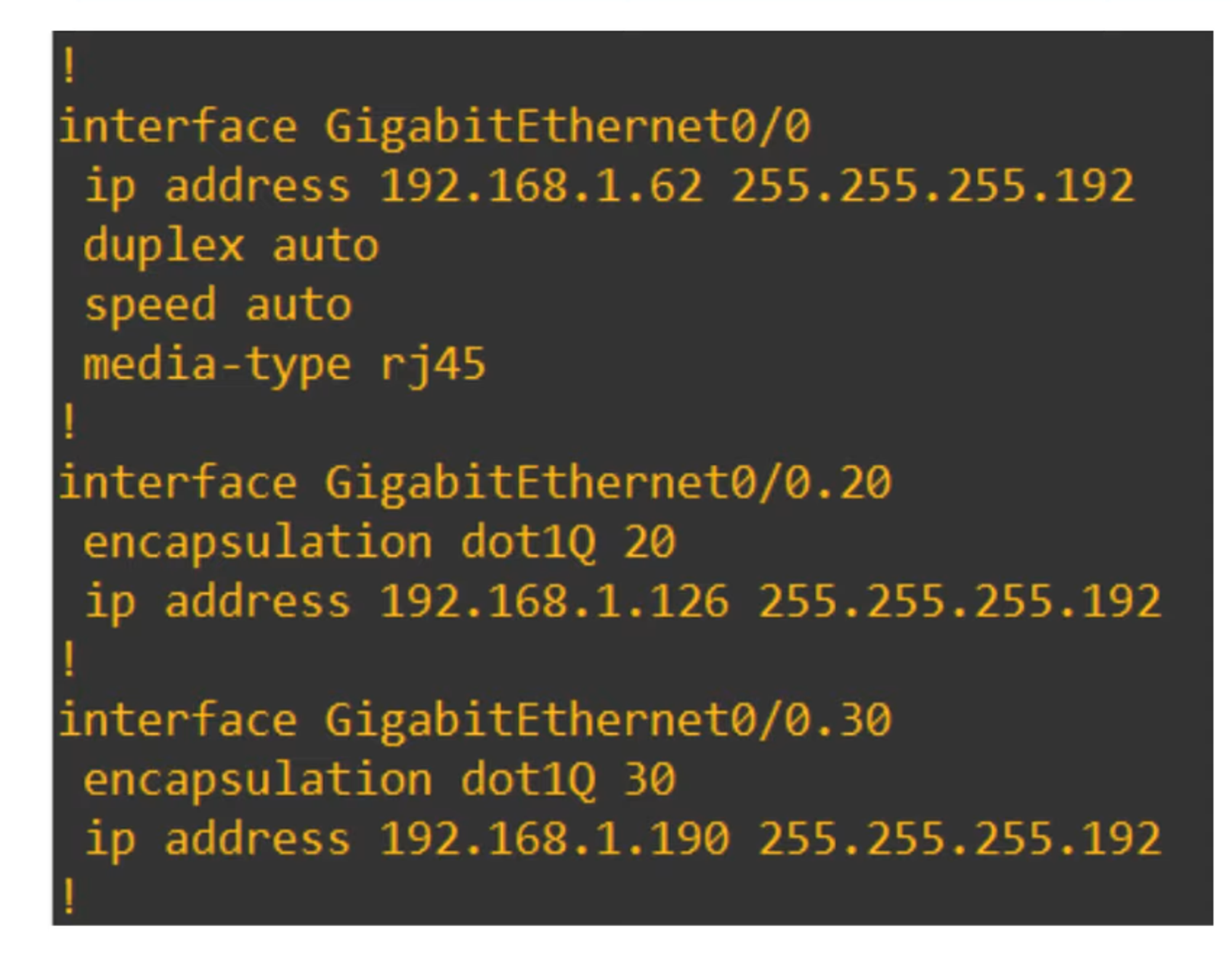
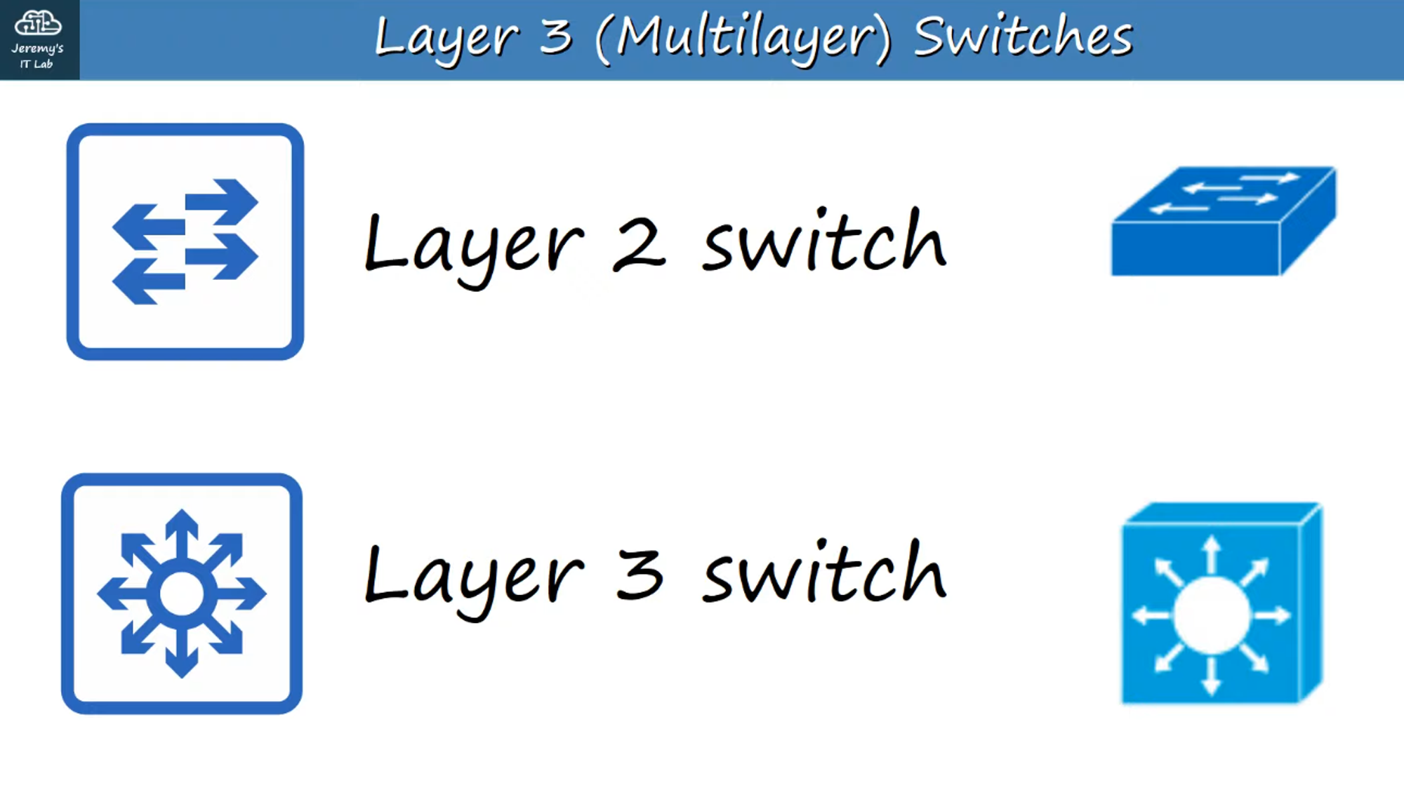
Layer 3 (Multilayer) Switches
-
A Multilayer Switch can perform both switching and routing functions.
-
It operates at Layer 3 of the OSI model (Network Layer), meaning it is capable of routing IP packets.
-
You can assign IP addresses to Layer 3 virtual interfaces on a Multilayer Switch, similar to a router.
-
SVIs (Switch Virtual Interfaces) allow you to create virtual interfaces for each VLAN and assign them IP addresses.
-
The switch can perform inter-VLAN routing, eliminating the need for a router in some network designs.
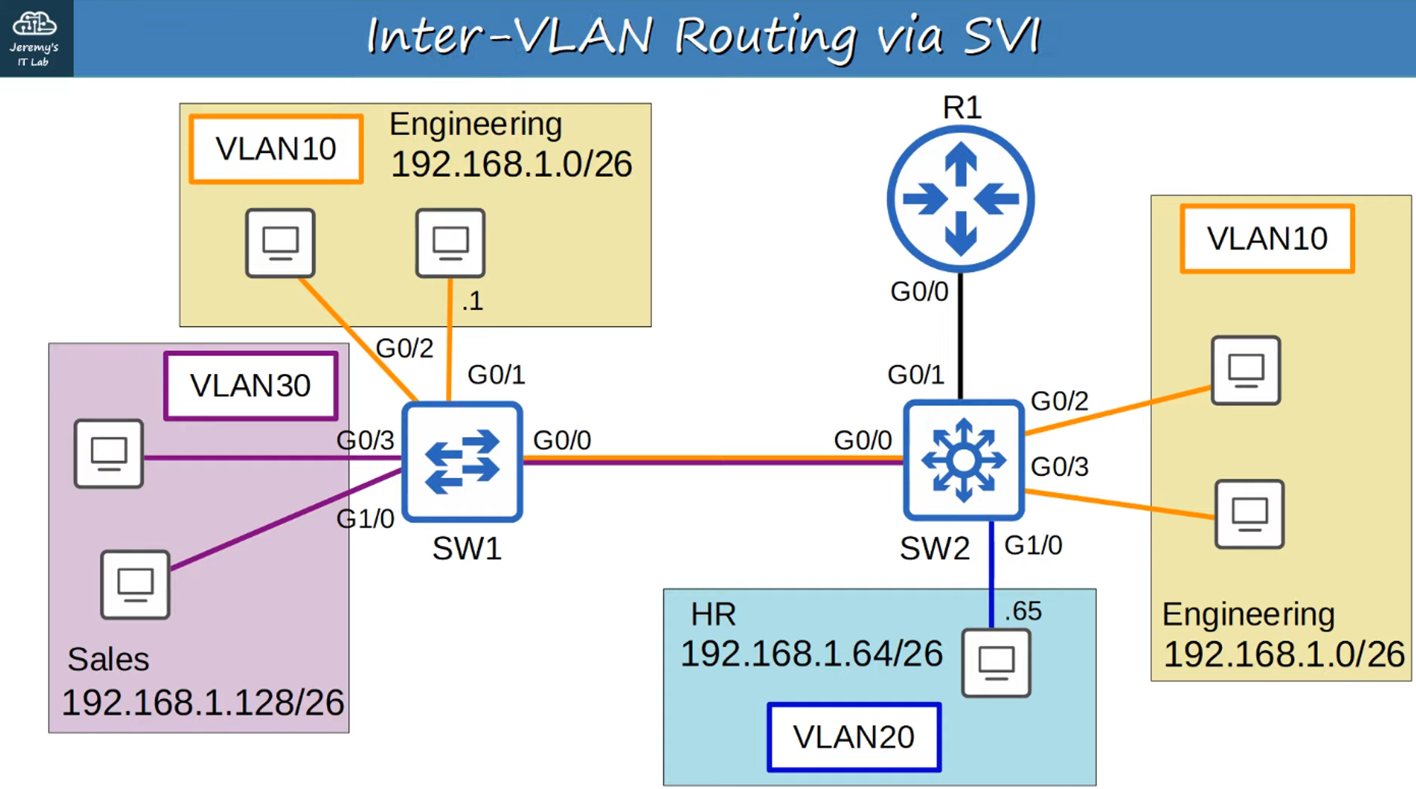
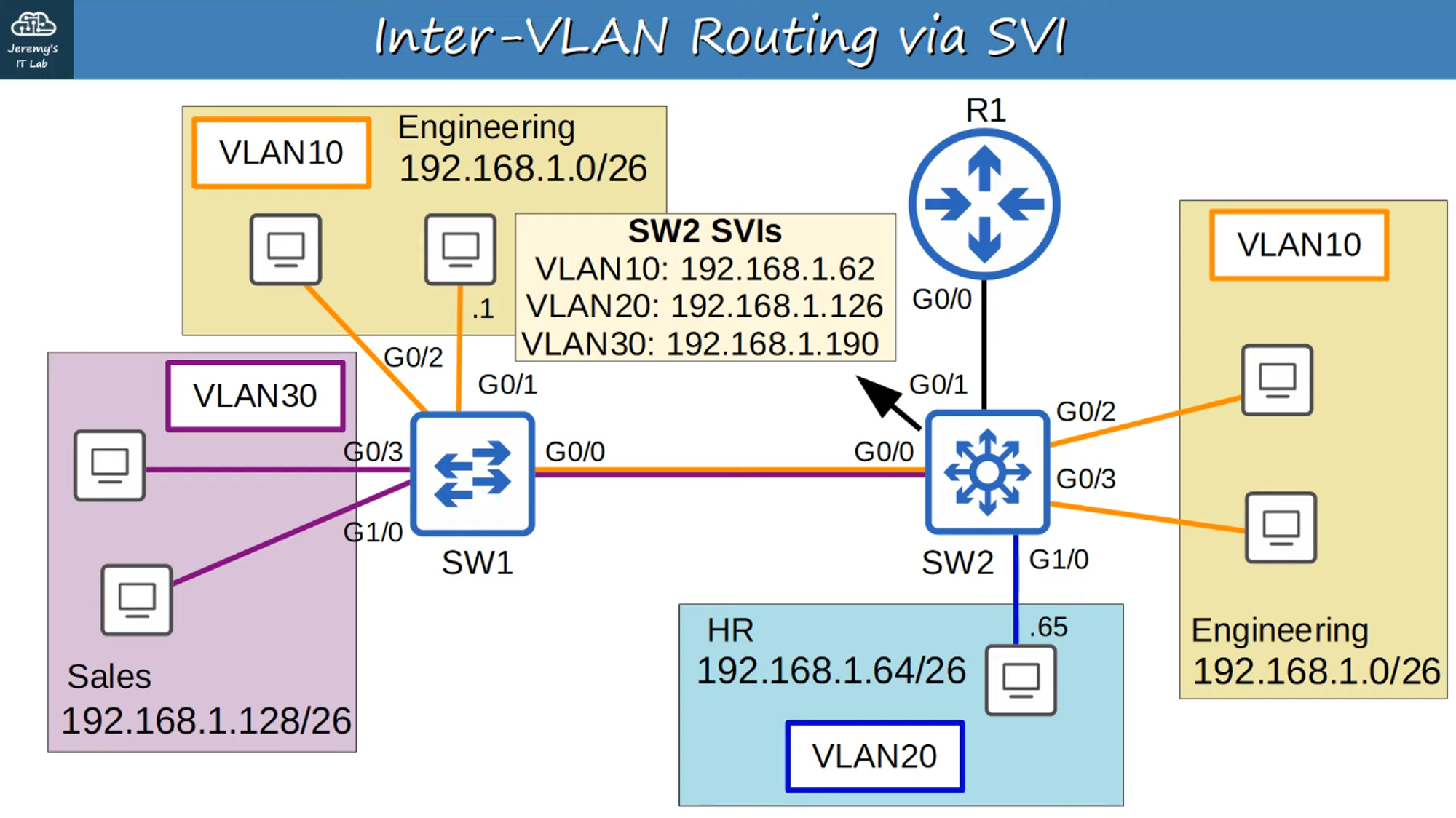
Replacing SW2 with a Layer 3 Switch
-
The multi-VLAN connections to R1 are replaced with a point-to-point Layer 3 connection.
Using SVIs for Routing
-
Configure each host to use the SVI (not R1) as the gateway address.
-
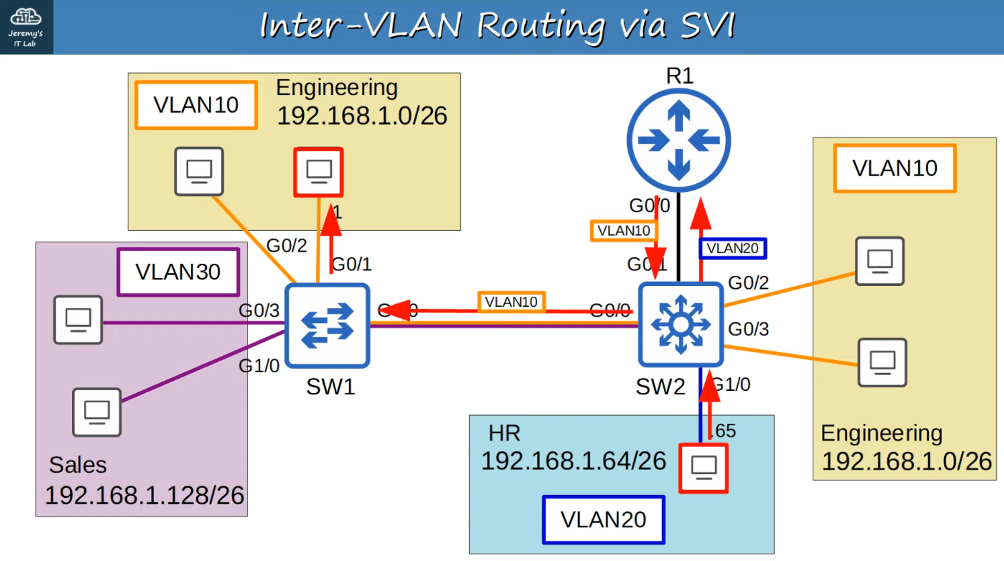
When hosts need to send traffic to different subnets or VLANs, they send traffic to the switch, which performs the routing.
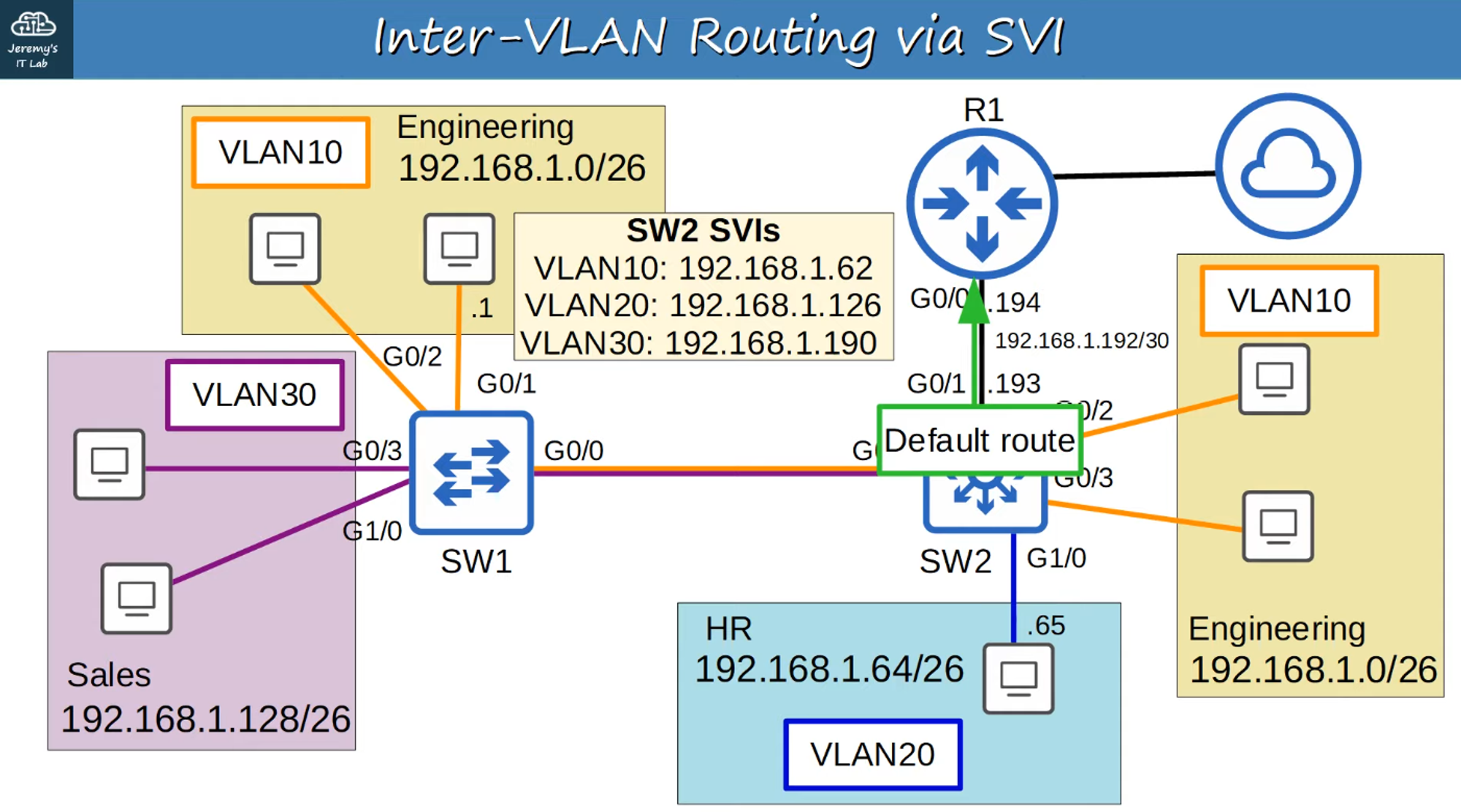
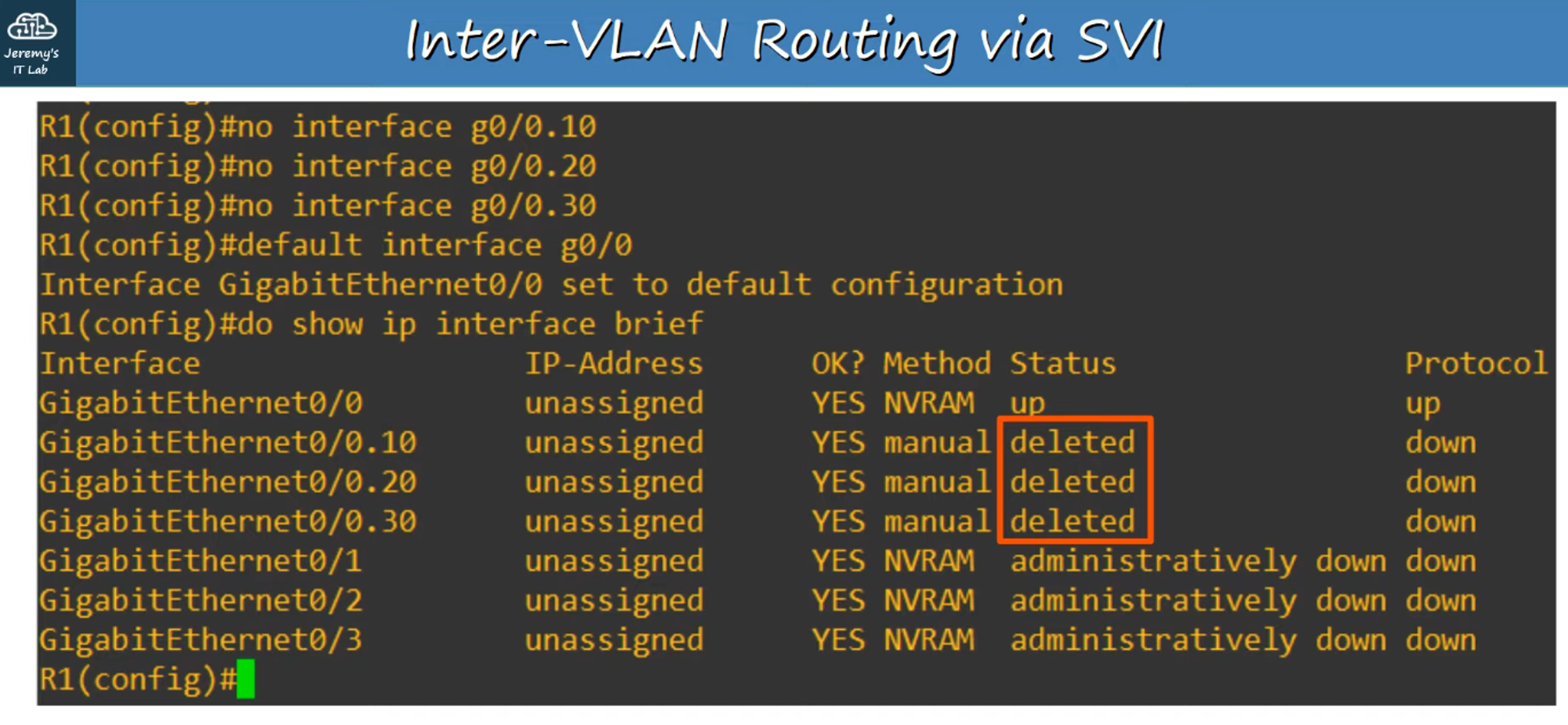
Clearing R1’s Configuration
-
To work with the Layer 3 point-to-point connection, clear the sub-interface configuration on R1:
#no interface <sub-interface id>— Removes the VLAN interface.#default interface g0/0— Resets the G0/0 interface to its default settings.- Then configure the default G0/0 interface on R1 with the IP address
192.168.1.194as shown in the network diagram.
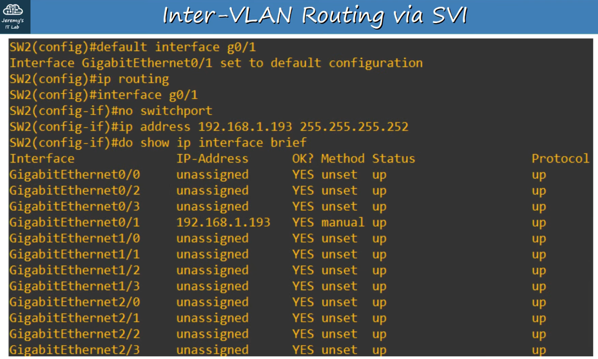
Configuring SW2 for Layer 3 Routing
-
Set up SVIs on SW2 and establish the Layer 3 point-to-point connection with R1.
-
Key commands:
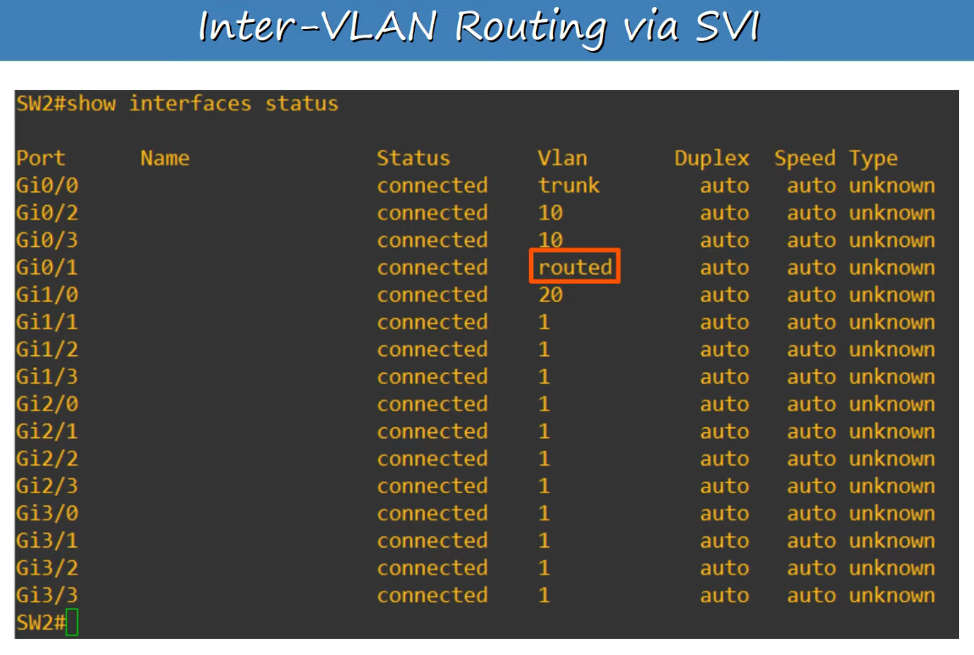
default interface <interface-id>— Resets the specified interface to its default settings.ip routing— Enables Layer 3 routing on the switch.no switchport— Converts the interface from a Layer 2 switchport to a Layer 3 routed port.
-
Configure a default route to R1 (
192.168.1.194) so that all traffic leaving the network gets routed through R1’s Gateway of Last Resort.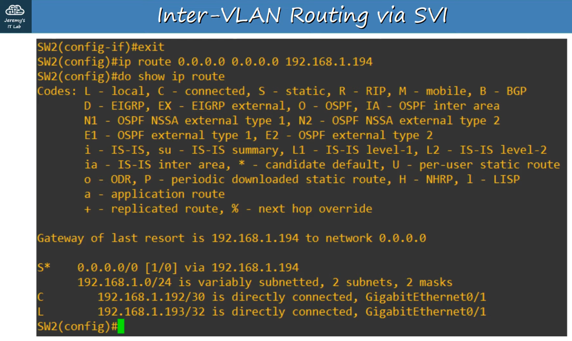
SVI Configuration on SW2
Switch Virtual Interfaces (SVIs)
-
SVIs are the Layer 3 virtual interfaces on a switch that allow routing between VLANs.
-
SVIs are shut down by default, so use the
no shutdowncommand to enable them.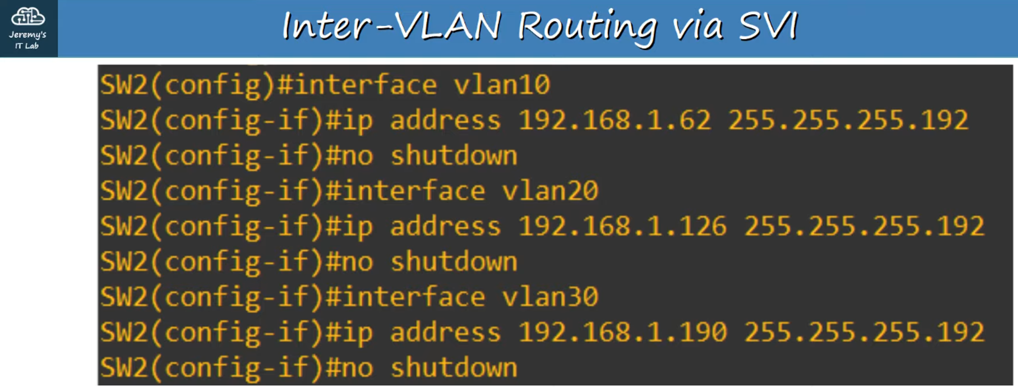
Troubleshooting SVI Status
-
If you create an SVI for an unknown VLAN (e.g., VLAN 40), the status/protocol will show “down/down”.
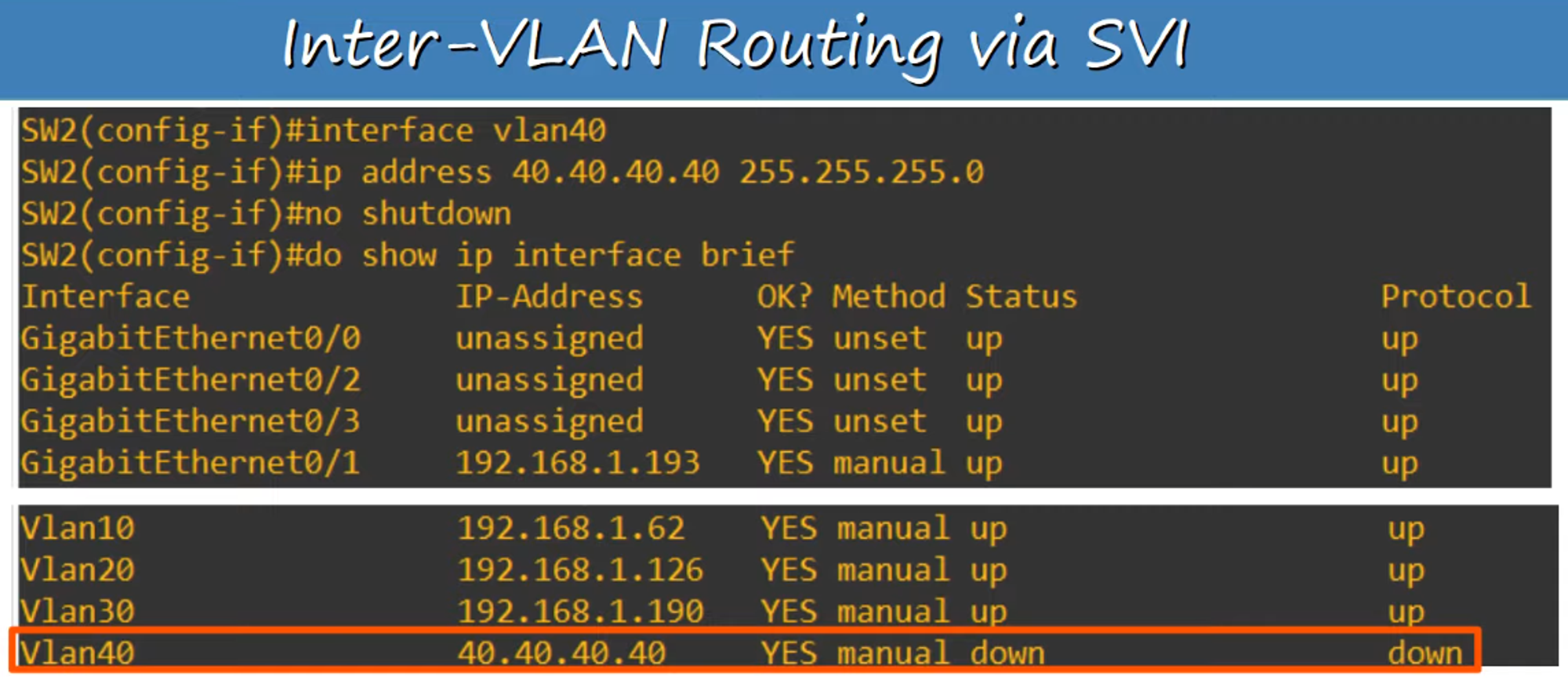
To bring an SVI to an “up/up” state, ensure the following:
-
The VLAN must exist on the switch.
-
At least one access port in the VLAN must be in an up/up state or a trunk port that allows the VLAN must be in an up/up state.
-
The VLAN itself must not be shutdown (use the
no shutdowncommand if needed). -
The SVI must also be enabled (
no shutdown).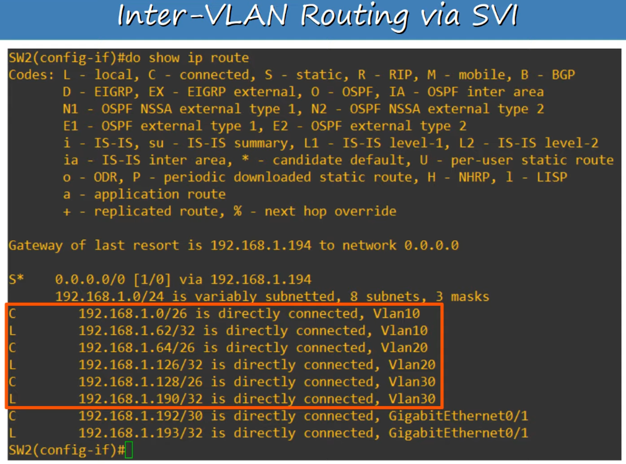
Final Setup: Layer 3 Switch SVI Trunk Replacement
- The VLAN trunk has been successfully replaced by a Layer 3 Switch SVI.
- All hosts can now communicate with each other (tested using ping) and access the external internet via R1.