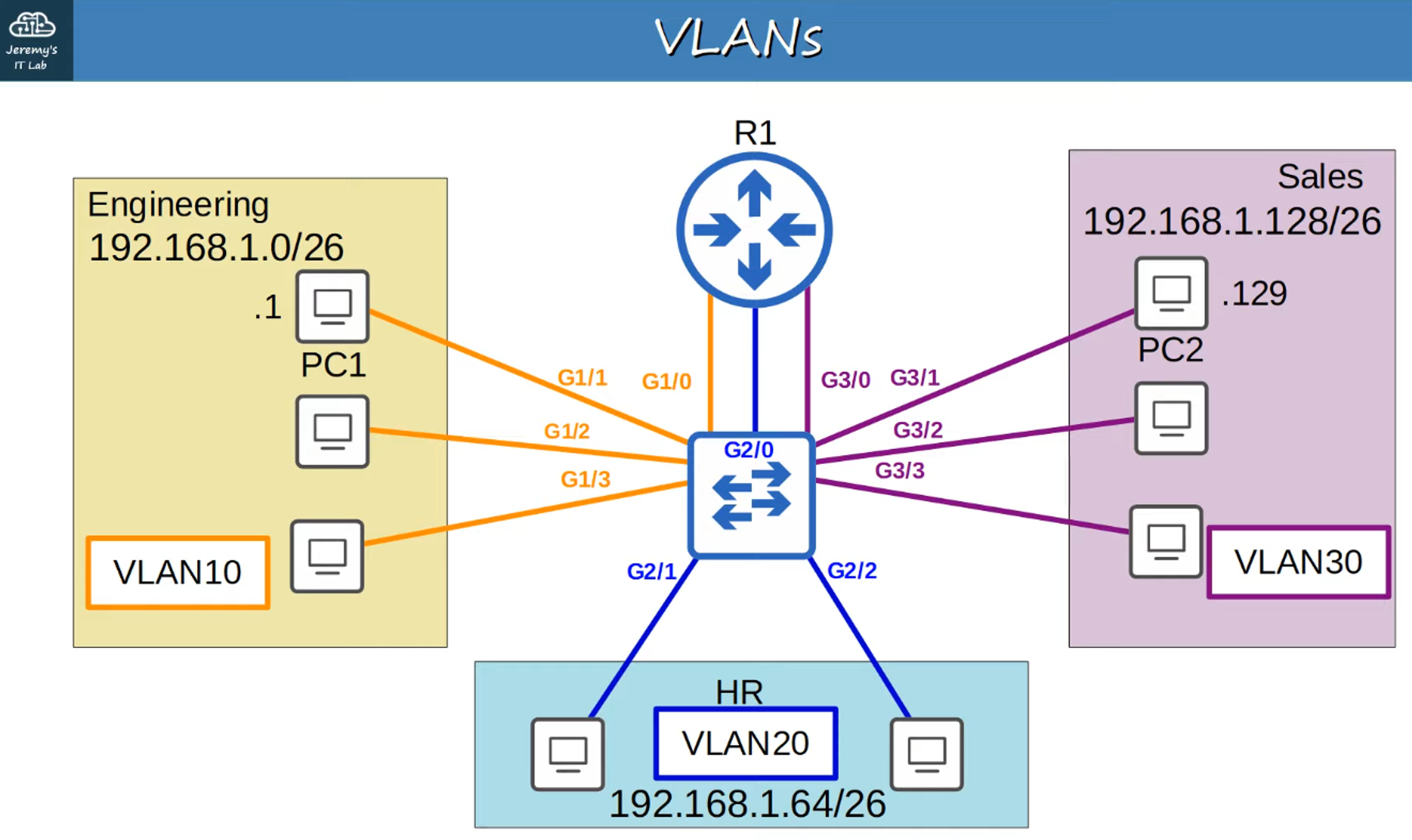
Review: Basic VLAN Topology
Let’s start with the basic VLAN topology from Part 1.
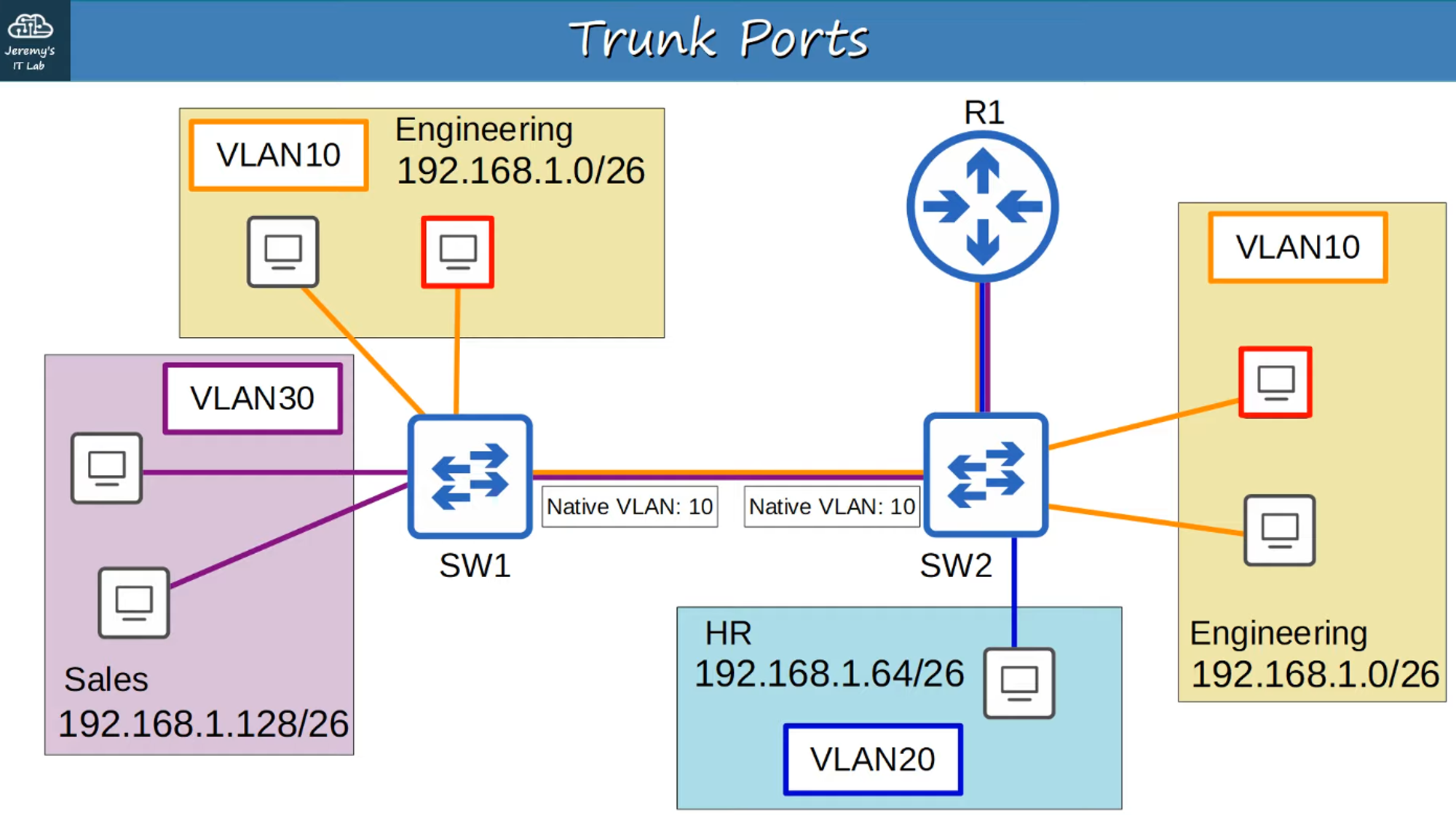
Expanded Network Topology
Now, consider a more complex network topology:
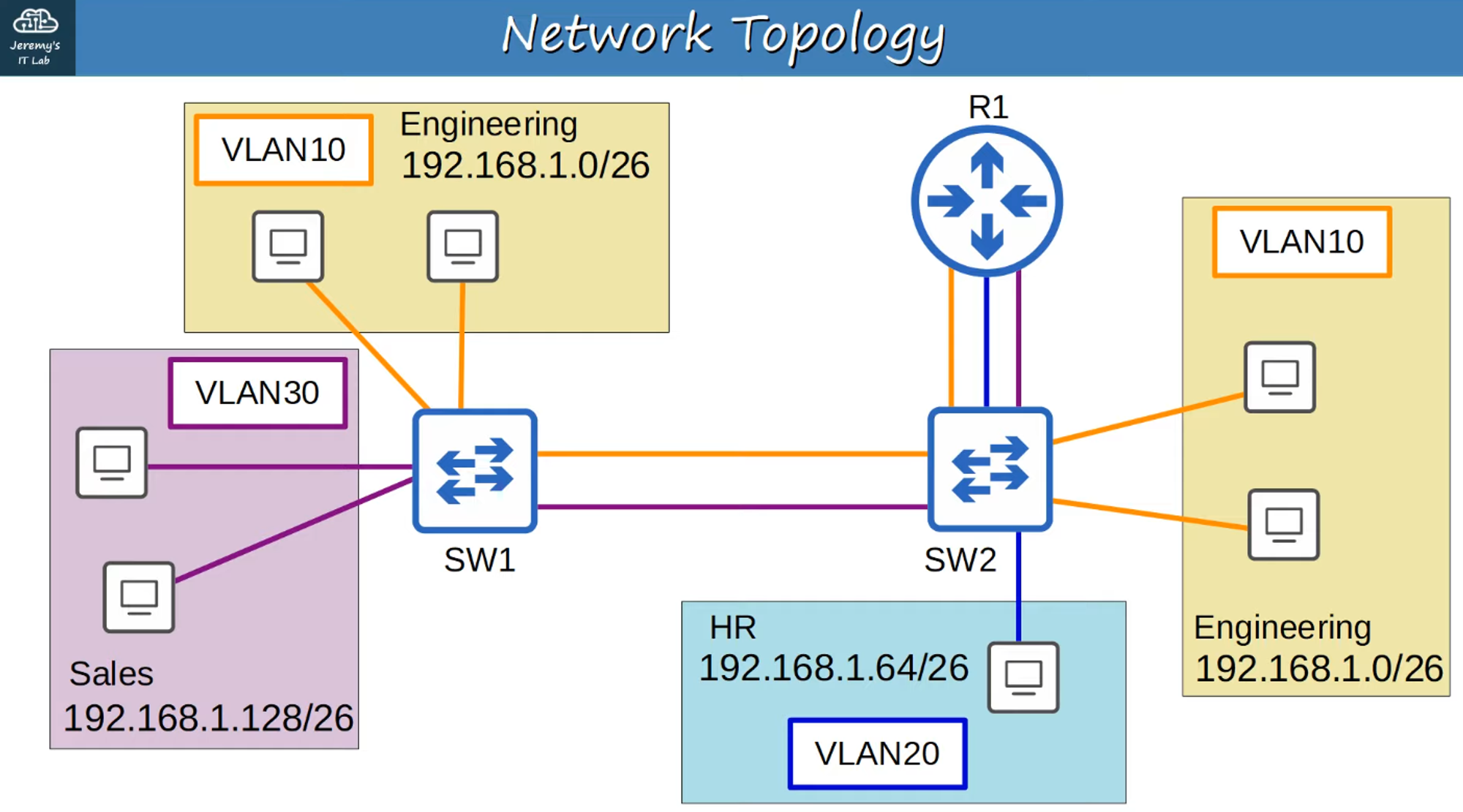
In this setup, we have two switches (SW1 and SW2), with the Engineering department (VLAN 10) located at two different network locations.
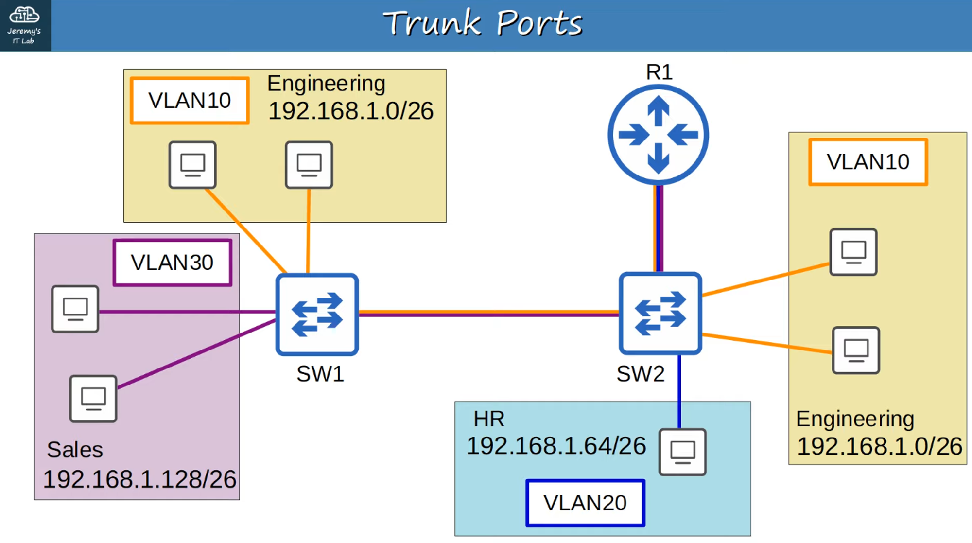
Trunk Ports
-
In a small network with only a few VLANs, it’s possible to use a separate interface for each VLAN when connecting switches to switches, or switches to routers.
-
However, as the number of VLANs increases, this method becomes inefficient. It leads to wasted interfaces, and often routers won’t have enough interfaces to support all VLANs.
-
Trunk Ports solve this problem by allowing multiple VLANs to share a single interface, effectively carrying traffic from multiple VLANs over a single connection.
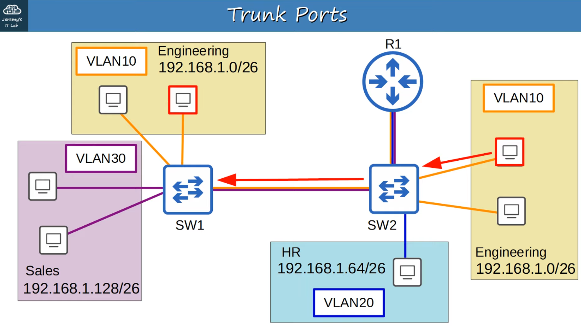
Example: A Trunk Port Carrying Multiple VLAN Connections
How Does Trunking Work?
When a packet travels over a trunk port, how does it know which VLAN to use? This is managed through VLAN Tags.
-
VLAN Tagging: Switches tag frames with VLAN information when they are sent over a trunk link, allowing the receiving switch to know which VLAN the frame belongs to.
-
Trunk Port: This port type uses “tagged” frames.
-
Access Port: This port type uses “untagged” frames.
VLAN Tagging Protocols
There are two main trunk protocols:
- ISL (Inter-Switch Link): A Cisco proprietary protocol that is now outdated.
- IEEE 802.1Q (dot1q): An industry-standard protocol developed by the IEEE.
ISL is rarely used today, even on Cisco equipment. For the CCNA exam, you need to focus on 802.1Q.
Ethernet Header with 802.1Q
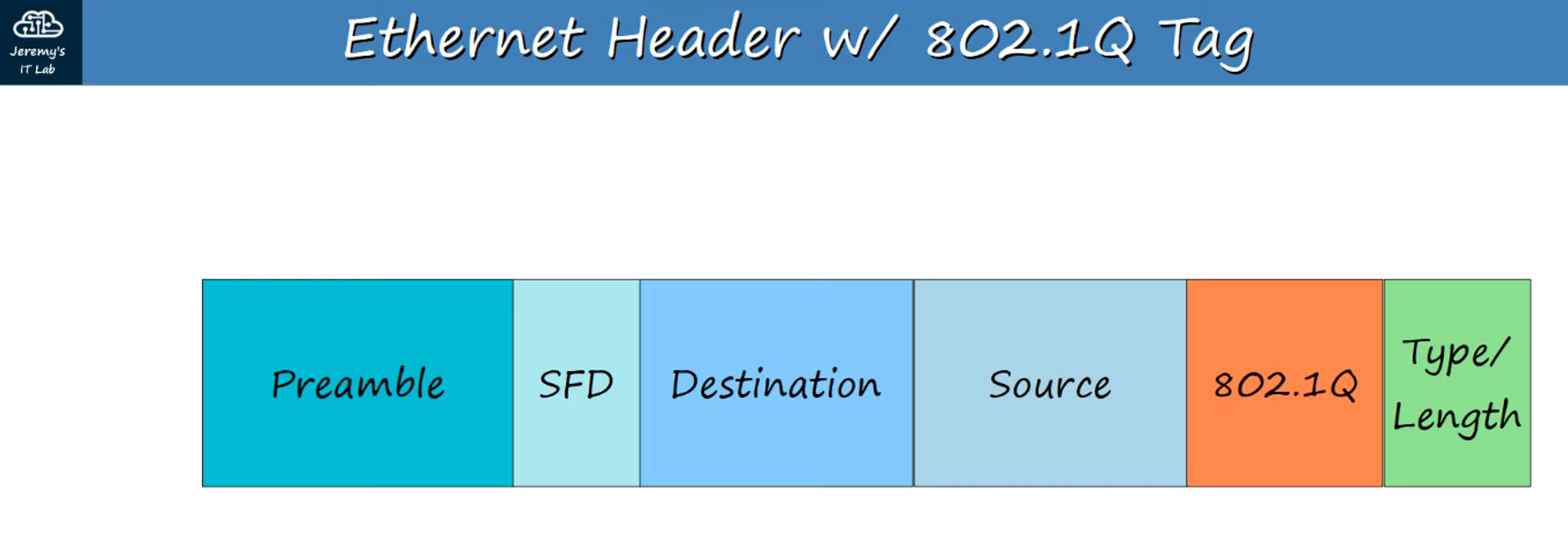
- The 802.1Q Tag is inserted between the Source MAC and Type/Length fields in the Ethernet frame.
- The tag is 4 bytes (32 bits) long and consists of two main fields:
- Tag Protocol Identifier (TPID): Identifies the frame as tagged with 802.1Q.
- Tag Control Information (TCI): Contains three sub-fields:
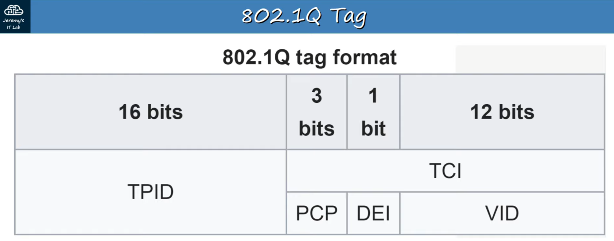
TPID (Tag Protocol Identifier)
- 16 bits (2 bytes) long, always set to
0x8100to indicate 802.1Q tagging.
TCI (Tag Control Information)
- PCP (Priority Code Point):
- 3 bits, used for Class of Service (CoS) to prioritize important traffic.
- DEI (Drop Eligible Indicator):
- 1 bit, used to mark frames that can be dropped if the network is congested.
- VID (VLAN ID):
- 12 bits, identifies the VLAN the frame belongs to.
- Allows for 4096 VLANs (0-4095), but VLANs 0 and 4095 are reserved, so the usable range is 1-4094.
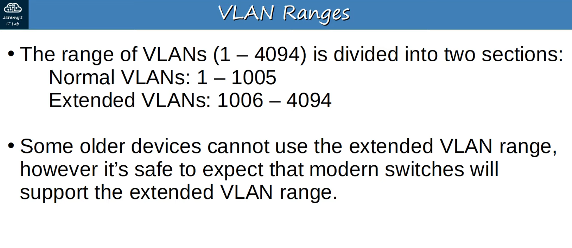
VLAN Ranges
Here’s a breakdown of VLAN ranges:
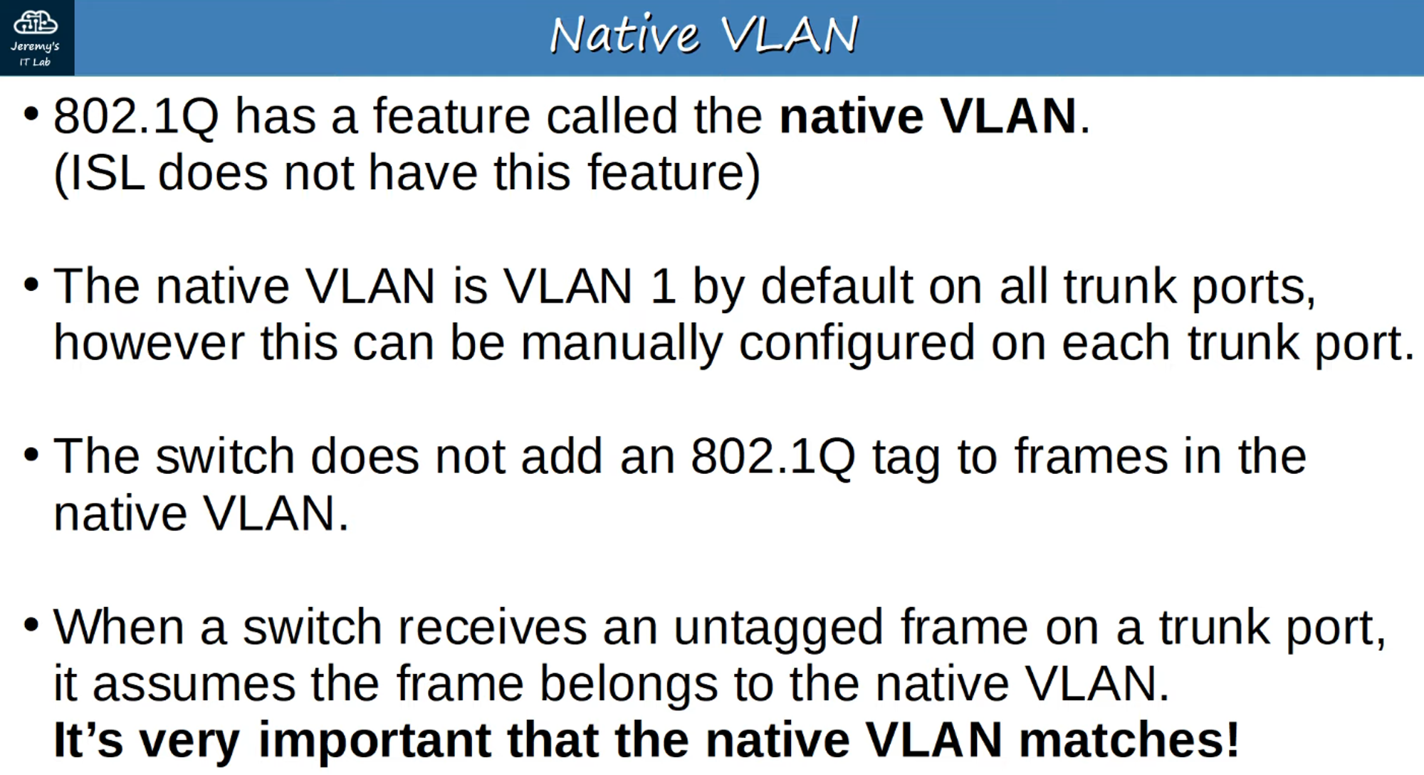
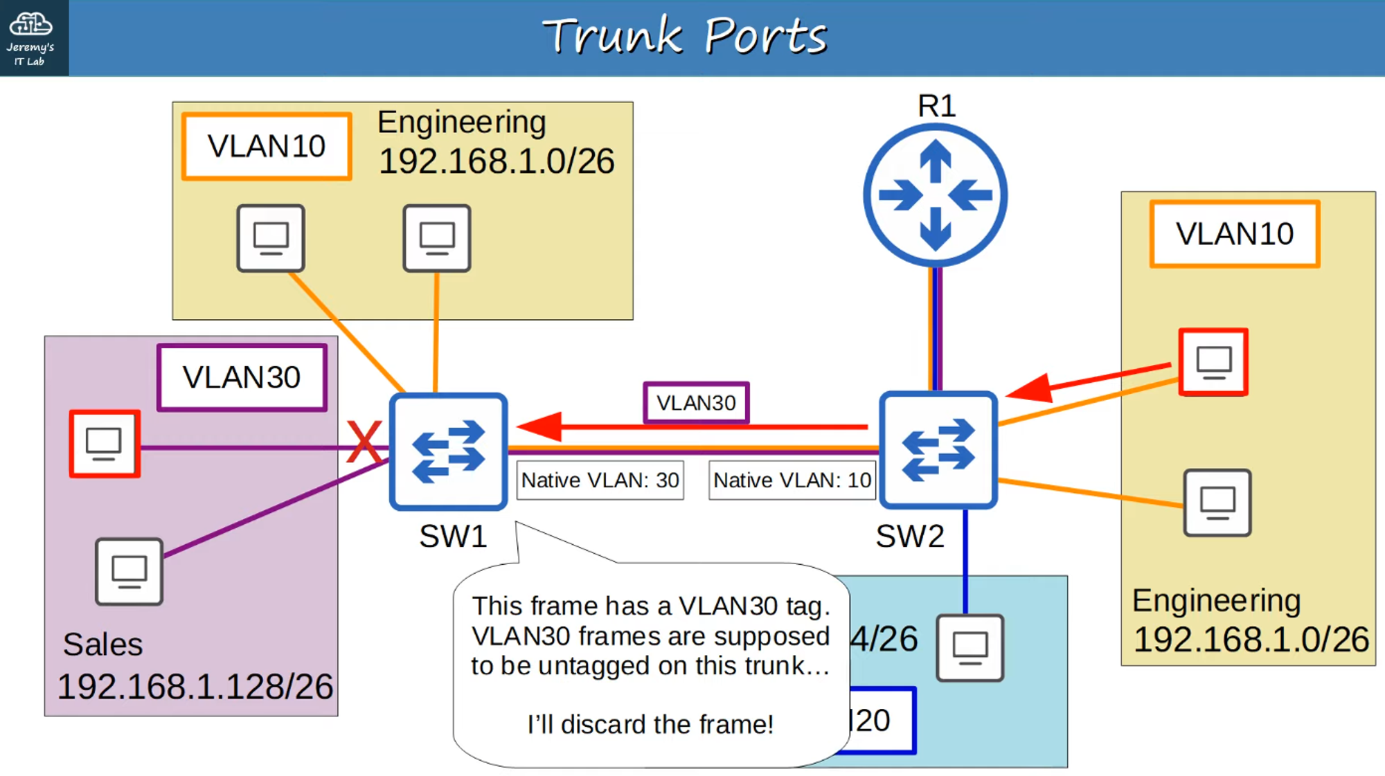
Native VLAN
The Native VLAN is the default VLAN for untagged traffic on a trunk port.
Configuring Trunk Ports
Step-by-Step Trunk Configuration:
-
Select Interface:
- Begin by selecting the interface you wish to configure as a trunk.
-
Set Trunk Encapsulation:
- Use
#switchport trunk encapsulation dot1qto set the encapsulation to 802.1Q.
- Use
-
Enable Trunk Mode:
- Use
#switchport mode trunkto manually configure the interface as a trunk port.
- Use
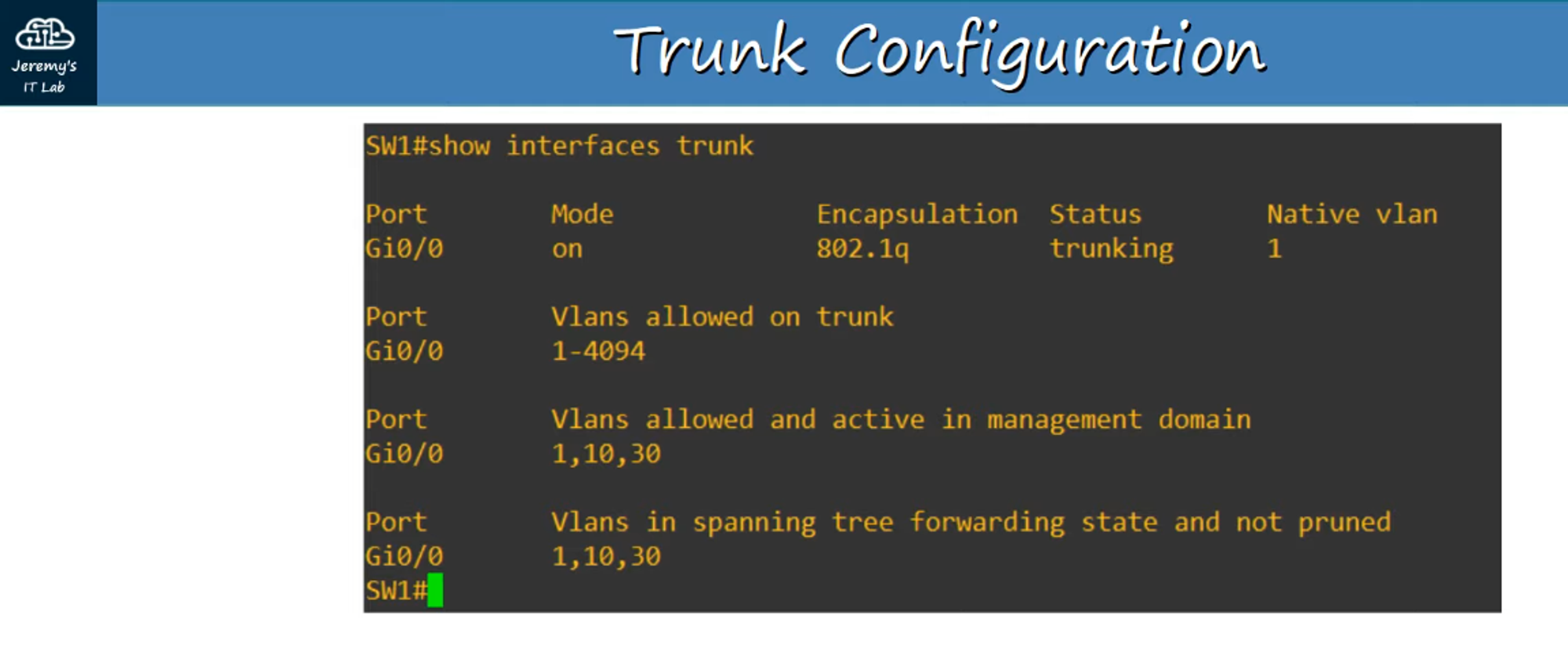
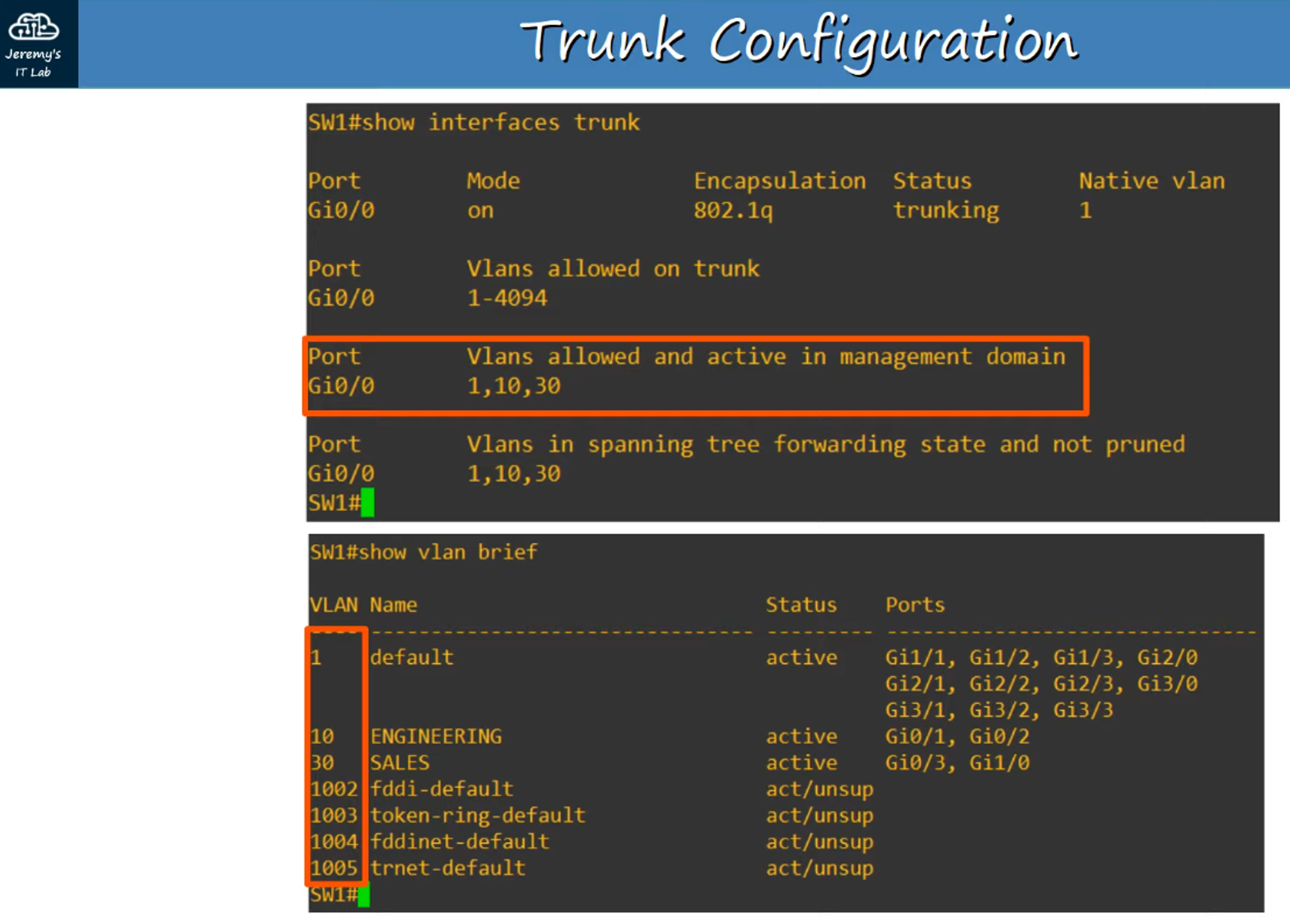
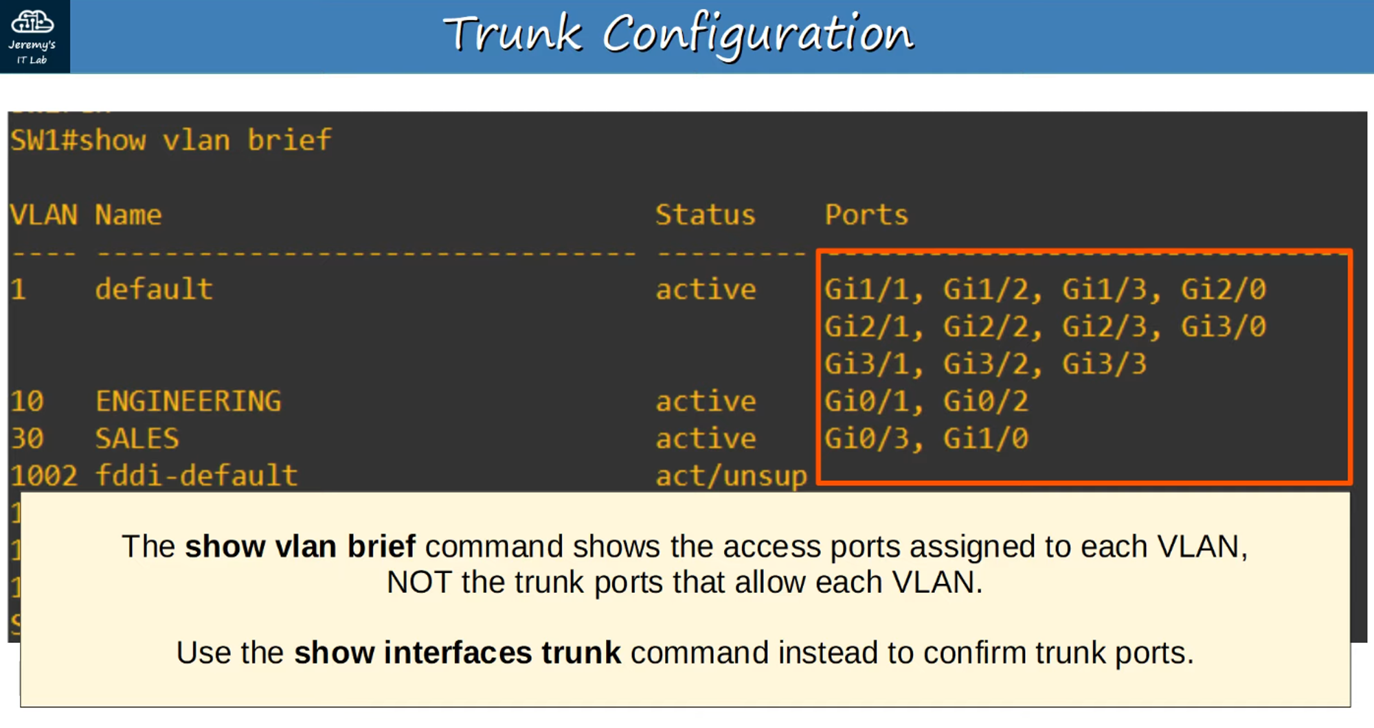
Verification
- Use the
#show interfaces trunkcommand to confirm which interfaces are set as trunk ports.
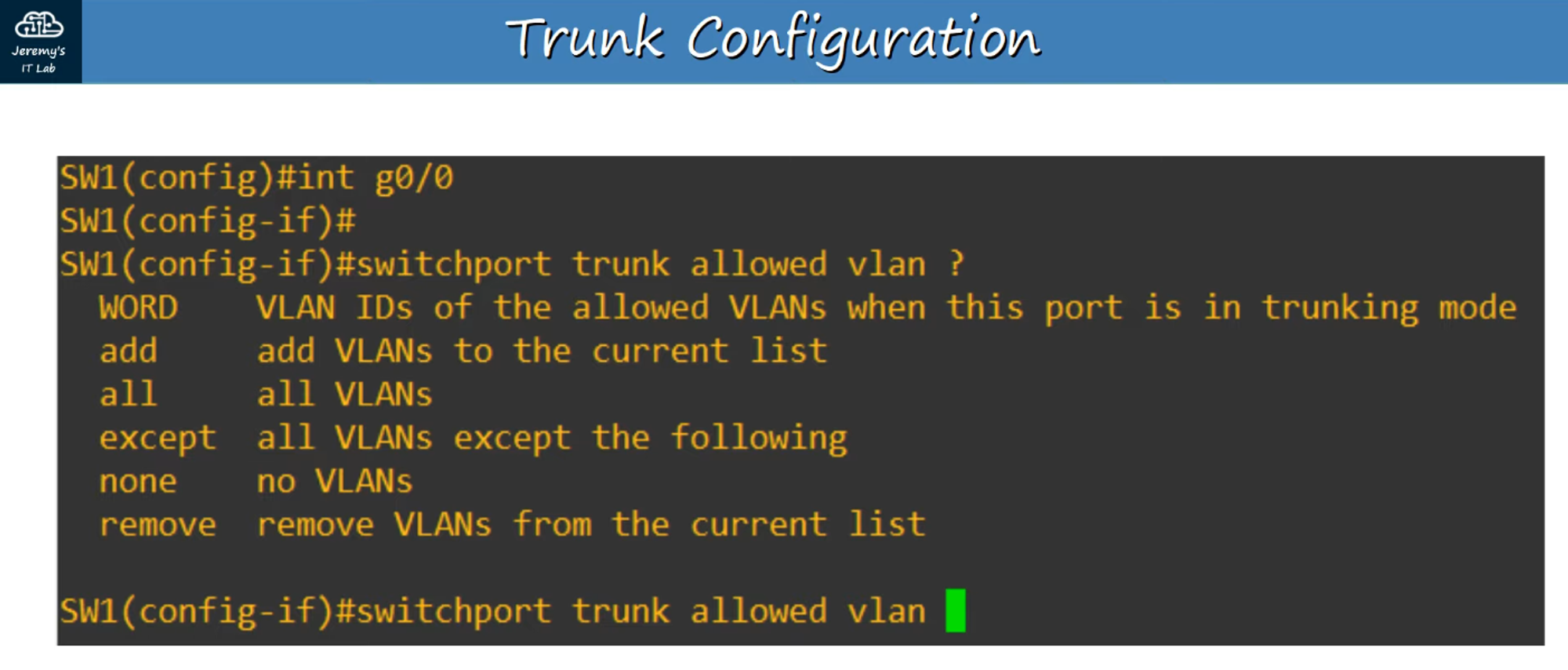
Allow Specific VLANs on a Trunk
- You can specify which VLANs are allowed to traverse a trunk link.
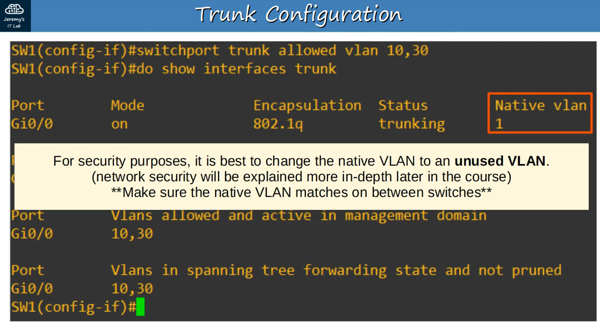
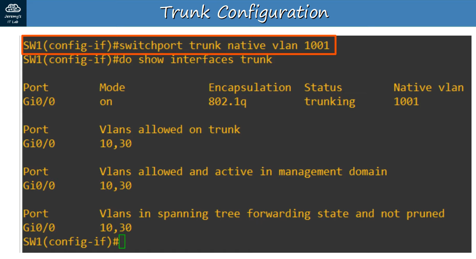
Change the Native VLAN
- The Native VLAN can be modified if needed.
Setting Up Trunks for This Network
For our example network, we’ll need to configure the following:
- SW1:
g0/0interface (already configured in the previous section). - SW2:
g0/0andg0/1interfaces.
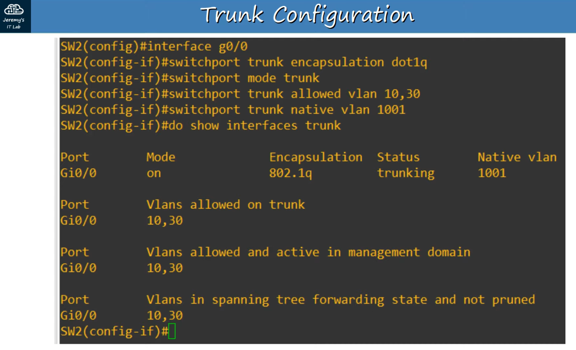
Configuring SW2 g0/0
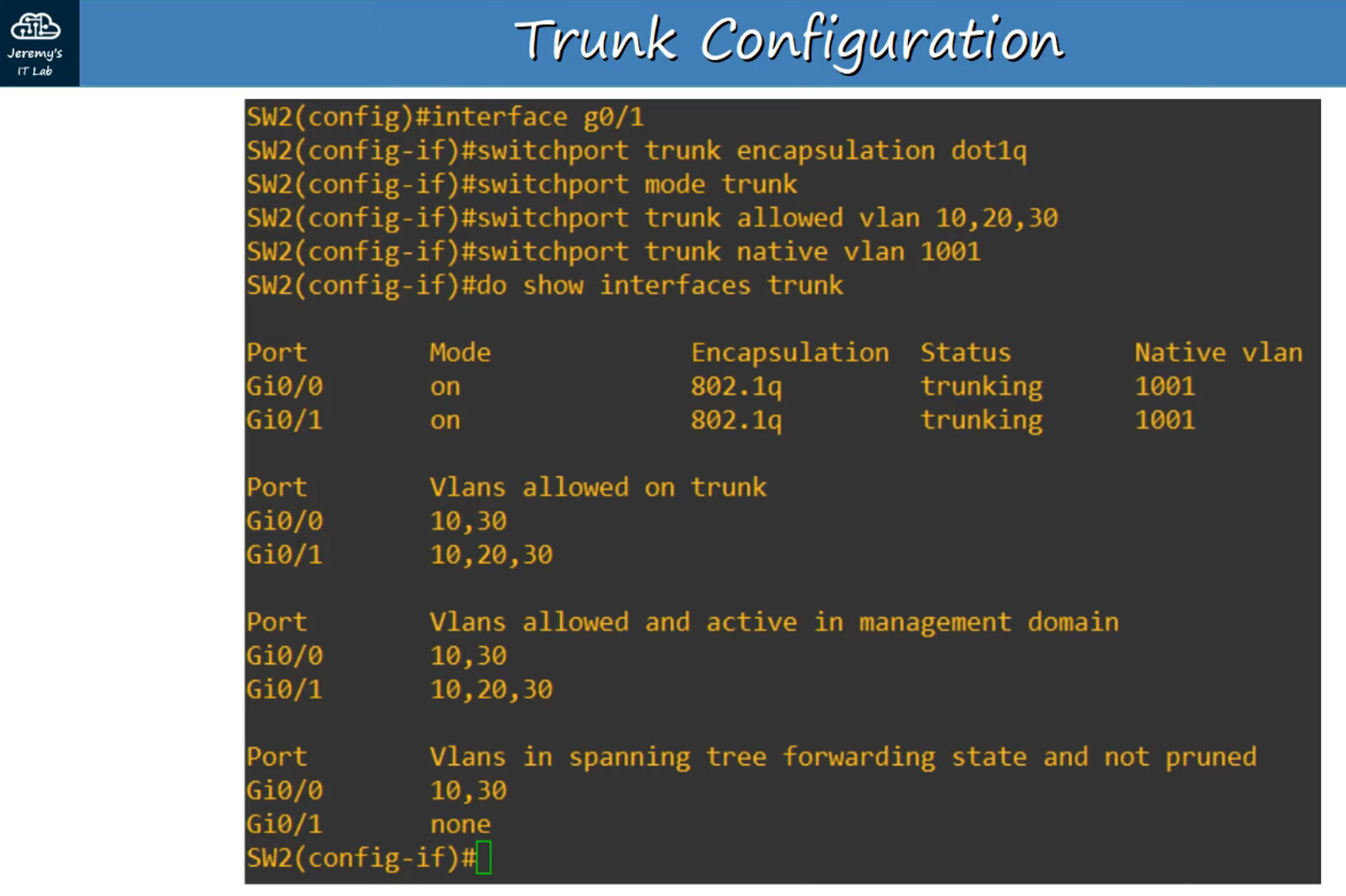
Configuring SW2 g0/1
What About the Router (R1)?
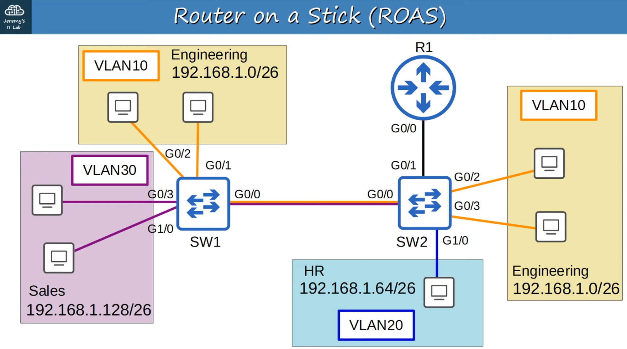
Router on a Stick (ROAS)
Router on a Stick (ROAS) is a method used to route traffic between multiple VLANs using a single physical interface on a router, leveraging sub-interfaces.
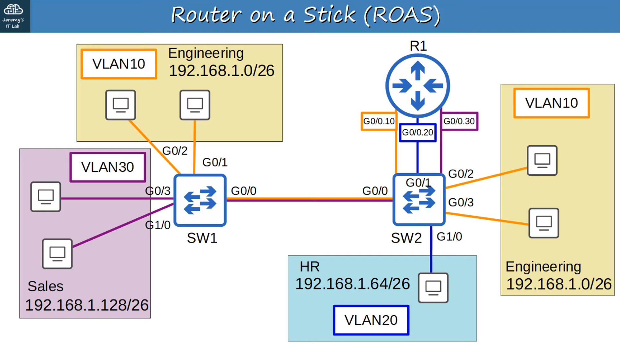
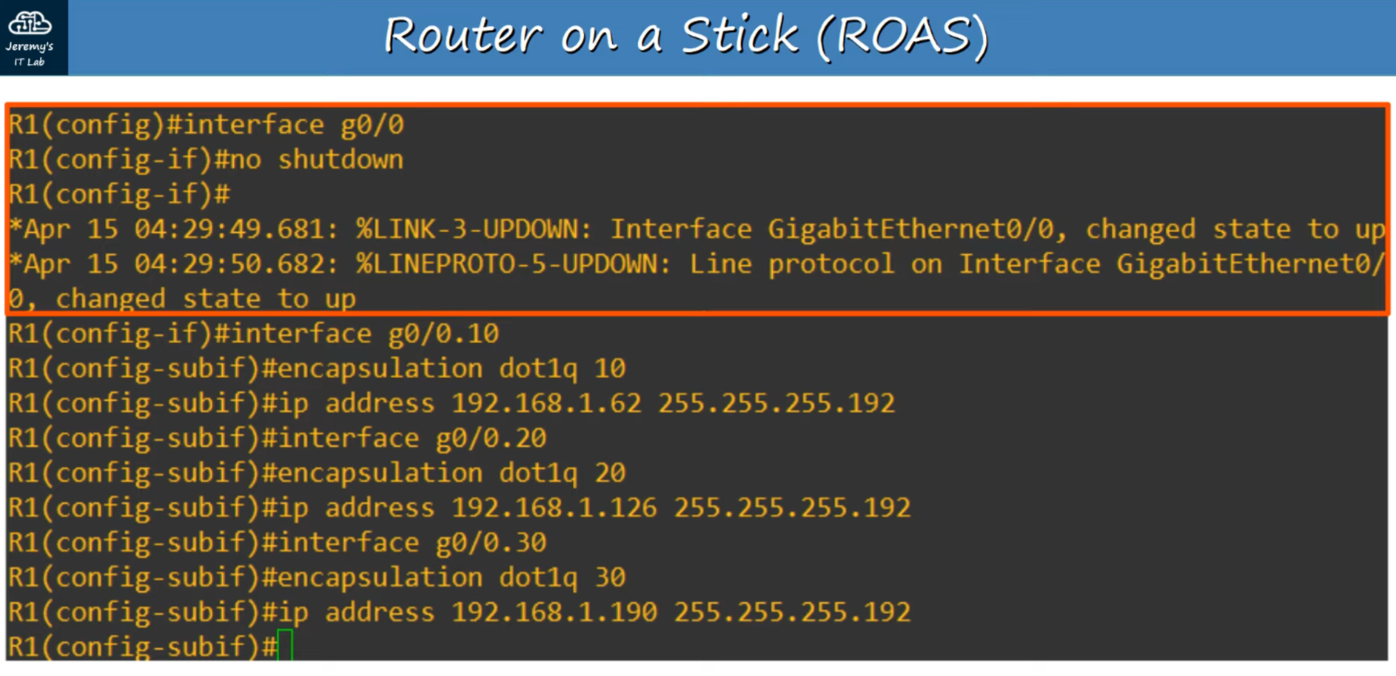
Sub-Interface Configuration
-
Sub-interfaces are named (e.g.,
0.10,0.20,0.30) according to the VLAN they serve. -
Assign IP addresses to sub-interfaces just like you would with regular interfaces, using the last usable IP address in each VLAN subnet.
-
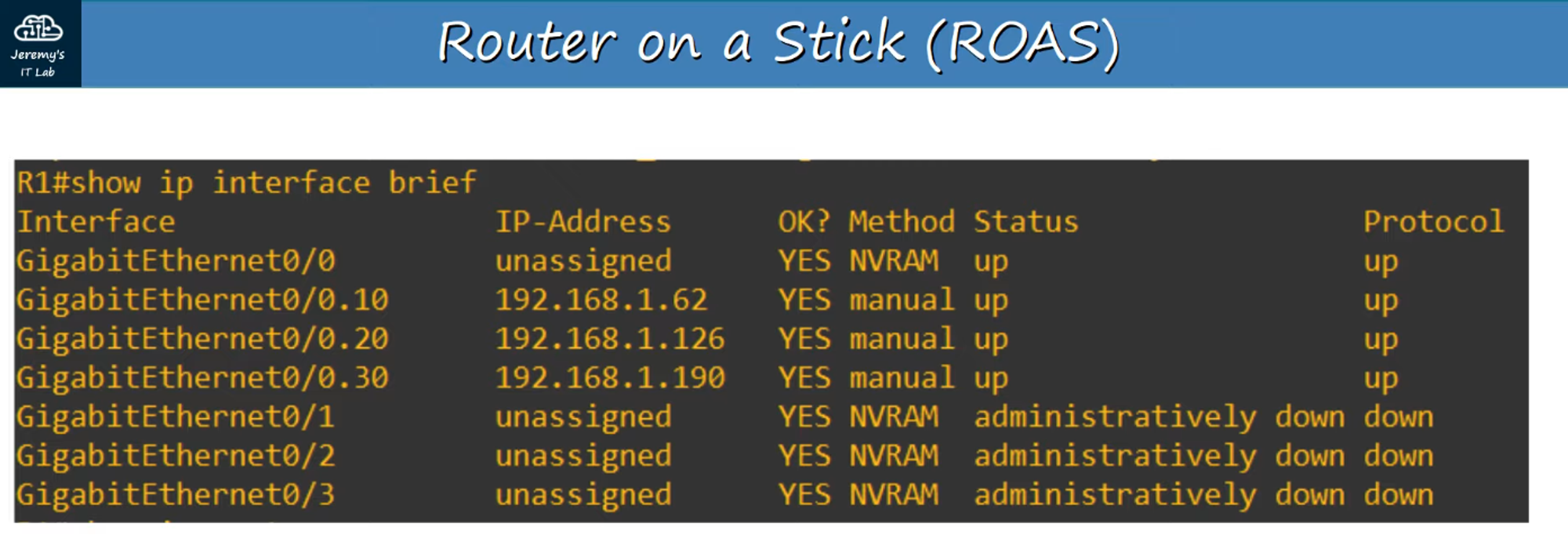
Show IP Interface Brief: Sub-interfaces will appear in the output of this command.
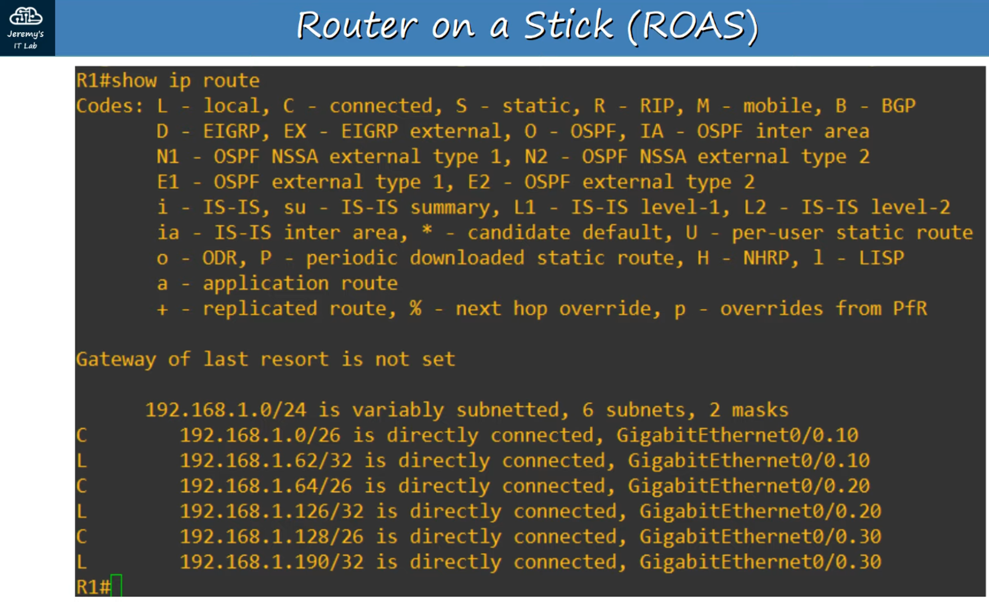
- Show IP Route: Sub-interfaces will also appear in the router’s route table.
ROAS Functionality
- Routing Between VLANs: ROAS allows the router to route between VLANs using a single interface and its associated sub-interfaces.
- Trunk Configuration: The switch interface connected to the router is configured as a trunk port.
- Sub-Interface Behavior: The router uses VLAN tags to determine which sub-interface to process incoming frames on and tags outgoing frames accordingly.
This method is highly efficient in VLAN routing, particularly in environments where conserving physical interfaces is necessary.